Understanding 3D Printing Tolerances

Content in this Article
3D Printing can look straightforward in CAD and still fail after printing, finishing or inspection. The useful question is not whether a process can make the geometry once, but whether the chosen material, orientation and acceptance method can deliver the required function repeatedly. This guide turns that decision into a practical review workflow.
- Define the operating environment, functional load, quantity and acceptance criteria before choosing a process.
- Treat dimensions and performance values as design-starting points; confirm the exact grade and supplier capability before release.
- Use a first article or pilot lot to lock inspection and process controls before scaling.
Start with requirements and process selection
What Tolerance Means in 3D Printing
The phrase "3D printing tolerance" is often handed around as if it referred to one universal process number. That framing is the first thing a production-oriented design team should drop. Additive manufacturing is a collection of processes — photopolymer curing, polymer powder sintering, metal laser melting, material jetting — each with its own layer formation physics, thermal history, shrinkage behaviour, and post-processing chain.
The goal is never the tightest possible tolerance everywhere. It is stable function at an acceptable cost. A drawing that calls out ±0.
Why Printed Dimensions Drift
Dimensional variation on a 3D-printed part rarely traces to a single cause. Each process family has its own dominant drift sources, and a design that compensates for the wrong one will fail in a way that looks random until the real cause is named.
| Process family | Dominant drift source | How it shows up |
|---|---|---|
| SLA / DLP / PolyJet | Cure shrinkage, wash distortion, post-cure growth | Feature size changes between wash and post-cure; large flats warp |
| SLS / MJF (polymer powder) | Thermal packing, cooling shrinkage, bed-position gradient | Same feature measures differently at bed centre vs. edge |
| FDM | Bed adhesion, chamber temperature, extrusion width variation | First few layers dimension-locked to platform; warp on long spans |
| DMLS / SLM (metal) | Thermal expansion during build, stress relief, heat treatment | Part moves between build, stress relief, and final heat treatment |
| Binder jet metal | Green-state shrinkage on sintering | Bulk shrink 15–25% — compensation must be built into CAD |
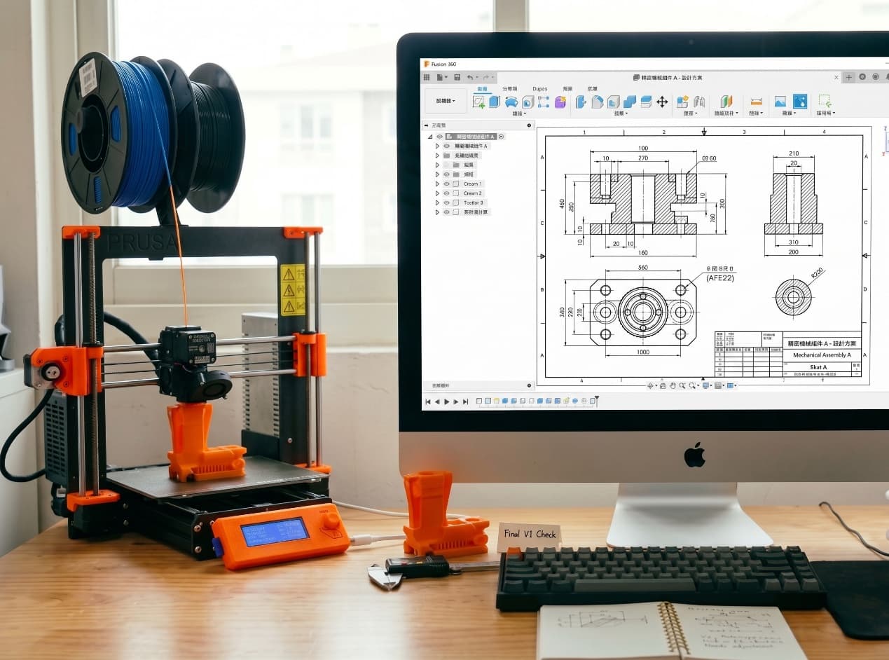
3D Printing: define requirements before selecting a process
Connect requirements, process decisions and inspection before the first build to reduce late design changes.
- 1Requirements
Function, service environment, quantity and failure risk
- 2Material and process
Material grade, build strategy, geometry and finishing
- 3Inspection
Critical dimensions, functional tests and lot records
Key design rules
Orientation Is Part of the Tolerance Strategy
Orientation is frequently handed to production as a scheduling decision. In reality, it is a tolerance decision. A circular feature printed with its axis vertical will come off the machine with a different profile than the same feature printed horizontally, because vertical circles are built as stacked layers (visible stepping, tighter diametric tolerance) while horizontal circles are built as sintered or cured arcs (smoother walls but sensitive to droop on the overhang-side surface).
The consequence for the design team is concrete: any tolerance-sensitive feature should be flagged for orientation review before the quote is treated as final. If a hole pattern, sliding face, or sealing land is strongly orientation-dependent, that dependence belongs in the design conversation, not in the post-mortem after the first build fails inspection.
Typical Planning Tolerances by Process
Planning tolerances are usually expressed as a first-inch allowance plus a percentage of nominal length. The table below consolidates the numbers most commonly cited as starting points across the main additive processes. Treat them as planning guidance, not specifications — a particular part on a particular machine with a particular finishing chain can land noticeably tighter or looser than the reference.
| Process | XY (first inch / 25 mm) | Z (first inch / 25 mm) | Length factor | Directional? |
|---|---|---|---|---|
| SLA / DLP | ±0.05 mm (±0.002 in) | ±0.127 mm (±0.005 in) | +0.1% of nominal | Yes — Z looser |
| PolyJet | ±0.127 mm (±0.005 in) | ±0.127 mm (±0.005 in) | +0.1% of nominal | Mildly |
| SLS (polymer) | ±0.25 mm (±0.010 in) | ±0.25 mm (±0.010 in) | +0.1% of nominal | Essentially isotropic |
| MJF (polymer) | ±0.30 mm (±0.012 in) | ±0.30 mm (±0.012 in) | +0.1% of nominal | Essentially isotropic |
| FDM | ±0.15 mm to ±0.50 mm | ±0.15 mm to ±0.50 mm | Machine-dependent | Yes — first layers tighter |
| DMLS / SLM (metal) | ±0.076 mm (±0.003 in) | ±0.152 mm (±0.006 in) | +0.1% of nominal | Yes — before heat treatment |
| Operation | Dimensional effect | Typical magnitude | Design action |
|---|---|---|---|
| Bead blasting | Material removed uniformly from exposed surfaces | 0.05–0.10 mm per surface | Add 0.05 mm to external walls if critical |
| Vapour smoothing (polymer) | Solvent reflow adds material on corners and fine features | +0.05–0.10 mm on small features | Subtract 0.08 mm from nominal if smoothing is specified |
| Sanding (manual) | Localised material removal, direction-dependent | 0.05–0.30 mm per surface | Reserve machining stock on sanded faces |
| CNC finishing (metal or rigid polymer) | Controlled removal to datum | 0.3–1.0 mm allowance | Print nominal oversize on datum faces |
| Primer + paint | Additive coating on every surface | +0.05–0.15 mm per surface (two coats) | Reduce nominal by coating thickness on mating features |
| Heat treatment (metal) | Isotropic shrink / growth, part-specific | Up to ±0.3% of nominal | Validate with witness coupon before production release |
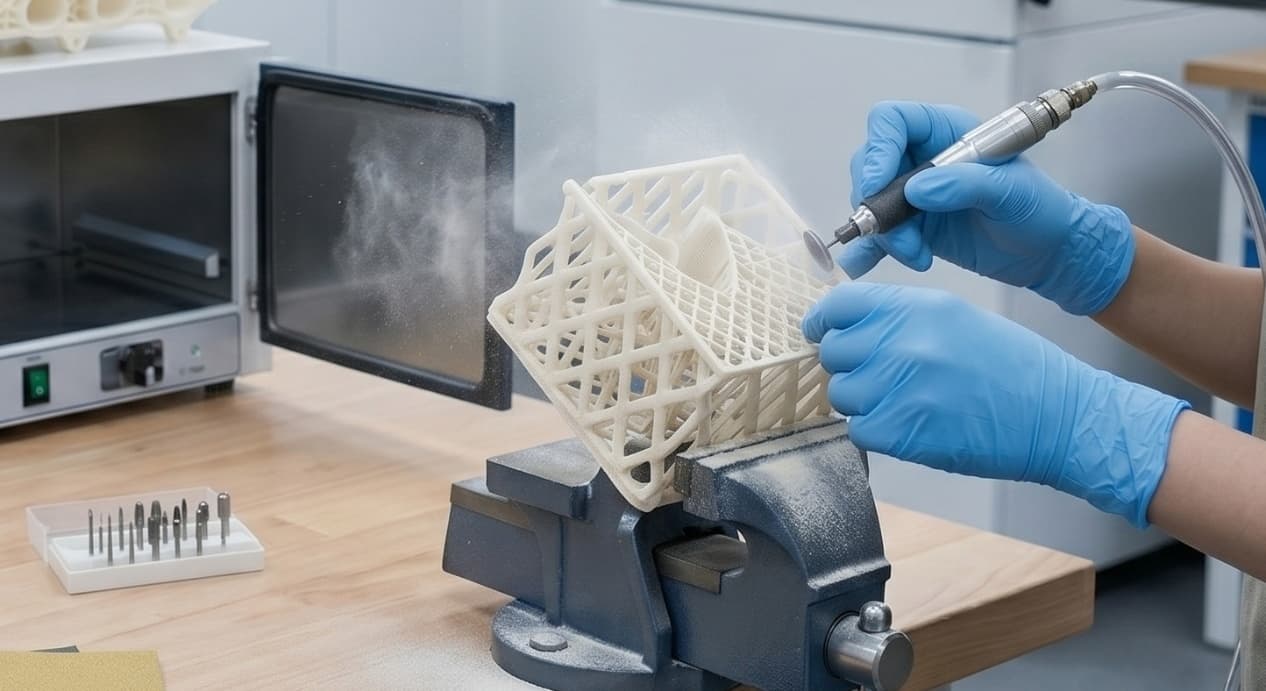
From prototyping and finishing to acceptance
Inspection: Match the Method to What You Can Afford to Be Wrong About
Inspection cost scales steeply with accuracy, and the wrong default is to pick the most accurate method the lab offers "just to be safe. " The useful default is to match the inspection method to the feature's consequence-of-failure, then add one step of margin. A dimension whose drift costs an hour of rework can live with callipers; a dimension whose drift costs a product recall needs CMM or CT.
| Method | Typical resolution | Relative cost | When to use |
|---|---|---|---|
| Callipers, micrometers, pin gauges | ±0.02 mm | 1× | Routine dimensional check on features with forgiving fits |
| Optical / vision measurement | ±0.01 mm | 2–4× | Flat features, 2D pattern verification |
| First-article inspection | Varies with instrument | 3–5× | Launch control, lot-to-lot qualification |
| CMM (coordinate measuring machine) | ±0.003 mm | 5–10× | Assembly-critical datums, mating features |
| 3D scanning (structured light) | ±0.05 mm over 100 mm | 4–8× | Whole-part deviation maps, large organic geometry |
| Industrial CT | ±0.02 mm, internal features | 15–30× | Internal channels, hidden porosity, high-consequence parts |
3D Printing: four checks before RFQ
- Function
State what the part must do and where it will be used
- Material and process
Name the required grade or performance range
- Design controls
Mark critical geometry, orientation and finishing
- Acceptance
Define dimensions, tests and required records
Pre-RFQ review: recommended practice and common mistakes
| Recommended practice | Common mistake |
|---|---|
| Tie tolerance to function, process, orientation, and inspection together | Apply one blanket tolerance to every dimension |
| State whether inspection happens before or after finishing | Assume as-printed dimensions equal final dimensions |
| Plan machining stock on critical metal surfaces | Expect DMLS to hit ±0.05 mm without a secondary op |
| Use a witness coupon on every heat-treated metal build | Rely on calibration from months ago |
| Flag orientation-sensitive features to the build team before quoting | Leave orientation to auto-nesting when sealing lands are involved |
| Transfer precision to a component that is already machined when it helps the system | Force every feature to be printed to final spec |
- Every fit-critical dimension has an explicit tolerance, not inherited from a title block default.
- Drawing calls out primary, secondary, and tertiary datums.
- Process is named on the drawing, with acceptable alternatives if any.
- Orientation-sensitive features are flagged for the build team.
- Inspection state (as-printed, blasted, smoothed, heat-treated) is stated for each tolerance call-out.
FAQ, further reading and sources
What should you define first for 3D Printing?
Define the operating environment, functional load, quantity and acceptance criteria before choosing a process. Those requirements determine the material, design rules and inspection plan.
Can the typical values in this guide be released directly on a drawing?
No. Use them for early design, then confirm the exact grade, supplier capability, DFM response and first-article result.
What should be locked before scaling production?
Lock the material, process settings, orientation, finishing and inspection method. Confirm that different lots reproduce the first-article result before scaling.
Next, explore 3D printing services, materials, online quoting, and the related design guides linked below.