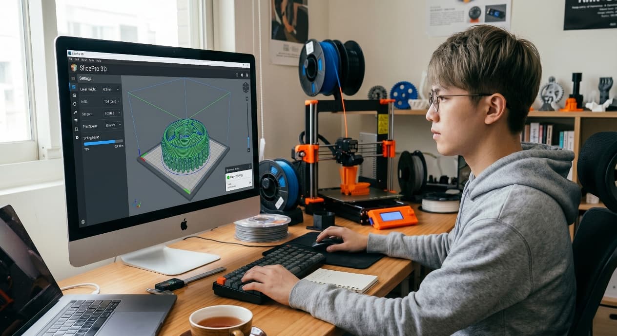
How to Design and 3D Print Flexible Parts
Content in this Article
3D Printing can look straightforward in CAD and still fail after printing, finishing or inspection. The useful question is not whether a process can make the geometry once, but whether the chosen material, orientation and acceptance method can deliver the required function repeatedly. This guide turns that decision into a practical review workflow.
- Define the operating environment, functional load, quantity and acceptance criteria before choosing a process.
- Treat dimensions and performance values as design-starting points; confirm the exact grade and supplier capability before release.
- Use a first article or pilot lot to lock inspection and process controls before scaling.
Start with requirements and process selection
When to Use Flexible 3D Printing
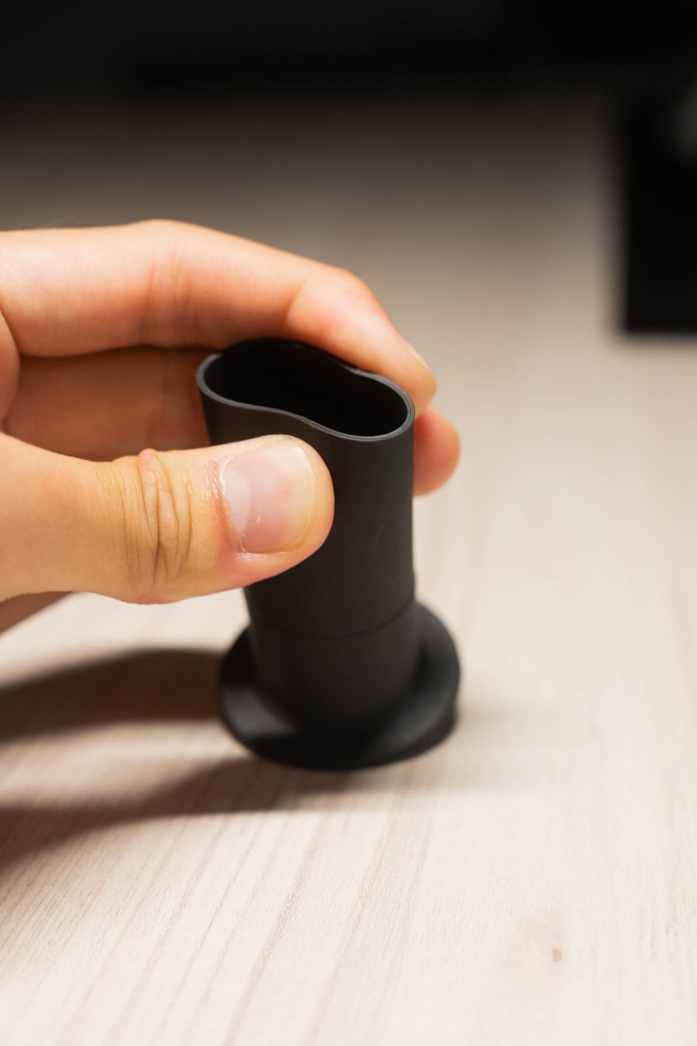
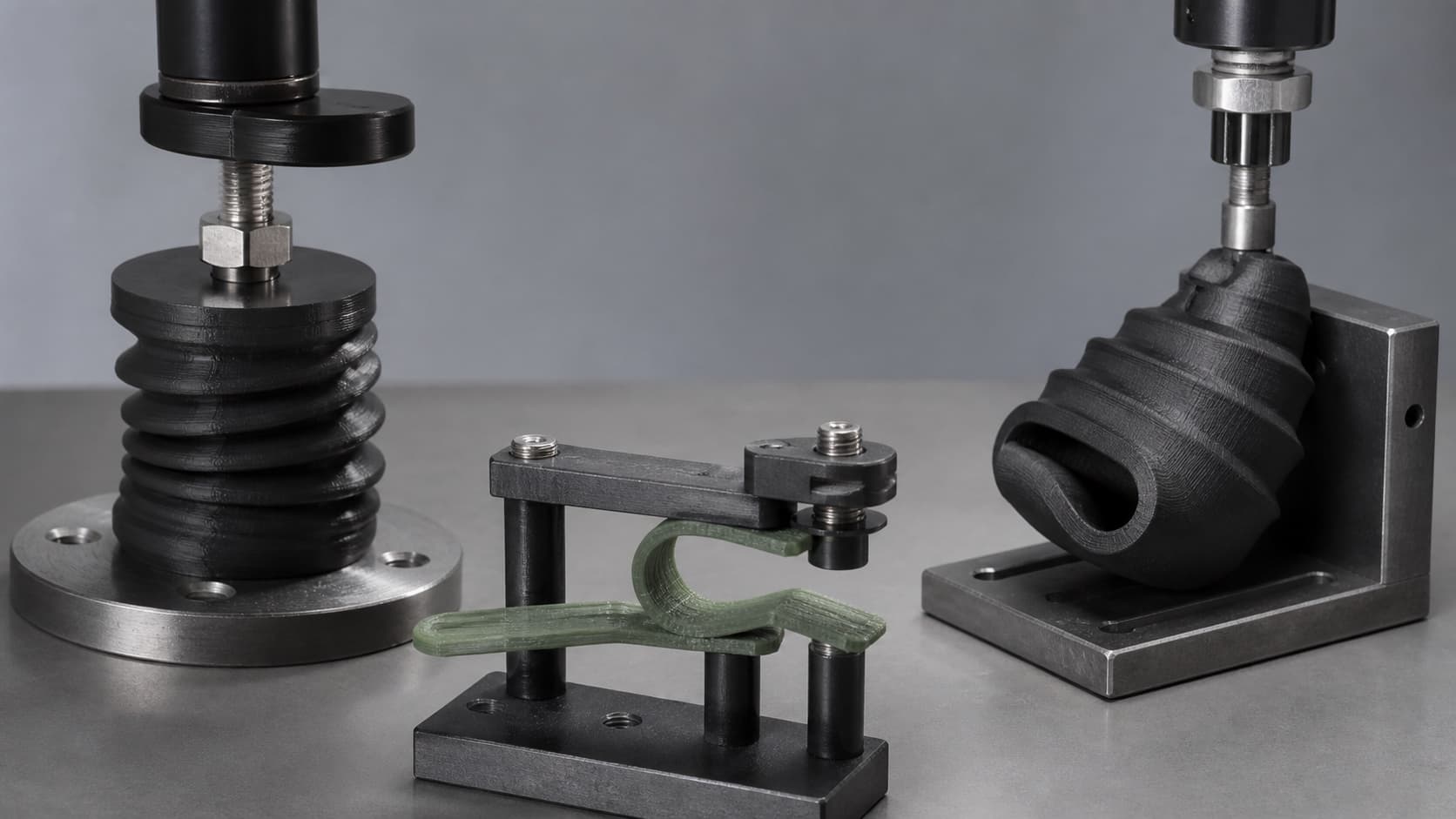
Flexible additive manufacturing makes sense when the design problem is not shape but controlled compliance, and when tooling economics do not work for the volume or the level of customisation involved. The sweet spot is low-to-mid volume functional parts that must bend, compress, or cushion in service — and custom-fit components where each unit is geometrically unique.
| Scenario | Why flexible AM fits | Expected duty / volume |
|---|---|---|
| Soft-touch grip on low-volume consumer product | Colour and geometry vary across SKUs | 10k–100k cycles, 100–2,000 units/SKU |
| Custom prosthetic or orthotic socket | Every unit is patient-specific | Daily use, 1 unit per patient |
| Compressible seal on pre-production hardware | Design-freeze before tool commitment | Hundreds of compression cycles for validation |
| Vibration-damping mount for prototype robotics | Design iterates weekly | 10k–1M cycles on validated design |
| Print-in-place living hinge for consumer device | Tooling would require two-shot mould | 100k+ actuation cycles |
Process Options for Flexible Parts
Four additive routes produce parts that bend, and they do not deliver the same durability. Flexible SLA resins are detail-rich and fast but sit at the low-cycle end.
3D Printing: define requirements before selecting a process
Connect requirements, process decisions and inspection before the first build to reduce late design changes.
- 1Requirements
Function, service environment, quantity and failure risk
- 2Material and process
Material grade, build strategy, geometry and finishing
- 3Inspection
Critical dimensions, functional tests and lot records
Key design rules
Geometry Rules for Longer Life
Durable flexibility comes from controlled strain distribution. A thickness step from 2 mm to 4 mm without transition creates a strain concentration at the boundary that is often 3–5× the nominal bending strain; the crack initiates exactly there on cycle one hundred or cycle one thousand.
| Feature | Recommended geometry | Why it matters |
|---|---|---|
| Thickness transition (rigid ↔ flex) | Taper length ≥ 3× Δ thickness | Avoids 3–5× strain spike at abrupt step |
| Bend-root radius | ≥ 1.5× local thickness | Sharp corners nucleate fatigue cracks; round corners distribute strain |
| Minimum flex section | ≥ 1.5 mm for TPU powder; ≥ 1.0 mm for FDM TPU | Thinner walls amplify strain amplitude at the same deflection |
| Hole / logo placement | ≥ 3× hole diameter away from flex path | Holes raise local strain by 2–3× |
| Flex length vs. deflection | Flex length ≥ 8× deflection distance | Keeps bending strain below 5%, the common fatigue safe zone |
Tolerancing Flexible Interfaces
A flexible part toleranced like a rigid machined part is toleranced wrong. The linear dimension on a snap zone is not what the assembly line measures — they feel the insertion force.
From prototyping and finishing to acceptance
Common Failure Modes and Their Design Fixes
| Failure mode | Where it starts | Design fix |
|---|---|---|
| Early crack at thickness step | The rigid-to-flex boundary | Graded taper ≥ 3× thickness delta; minimum root radius 1.5× thickness |
| Permanent set shifts interface fit | High-strain compression zones | Design below 30% static strain; specify rebound minimum; switch to higher-rebound grade |
| Rigid-flex delamination | Bond or transition interface | Mechanical interlock geometry; avoid pure adhesion at stressed seams |
| Layer-opening on fold | Fold line parallel to build layers | Rotate part so fold crosses layers; lock orientation in production |
| Assembly force out of window | Undefined functional tolerance | Tolerance on force, not on linear dimension; re-validate after finishing |
Pre-Release Validation Checklist
Use the list at design review and again before first production release. Each item protects against one of the failure modes above.
- Target Shore window, minimum rebound, and cycle target are written on the drawing.
- Material has been screened against the real cleaning / fluid / temperature environment.
- Every thickness transition is graded over ≥ 3× the delta; every bend root has a minimum radius of 1.5× thickness.
- Functional tolerance (force, compression ratio, or contact pressure) is specified instead of a single linear dimension.
- Build orientation is fixed and documented; fold lines cross the layer stack.
3D Printing: four checks before RFQ
- Function
State what the part must do and where it will be used
- Material and process
Name the required grade or performance range
- Design controls
Mark critical geometry, orientation and finishing
- Acceptance
Define dimensions, tests and required records
Pre-RFQ review: recommended practice and common mistakes
| Recommended practice | Common mistake |
|---|---|
| Define duty cycle before picking a material | Pick by Shore hardness alone |
| Tolerance interfaces on force or compression ratio | Tolerance flex parts with tight linear dimensions |
| Orient the fold line to cross layers, then freeze orientation | Let auto-nesting re-orient flex parts between batches |
| Screen for IPA, oils, UV, temperature before release | Assume datasheet values carry to the real service environment |
| Grade thickness transitions over ≥ 3× the delta | Step from 2 mm to 4 mm without taper |
- The function, service environment and failure risks for 柔性 3D 列印 are documented
- Critical dimensions and necessary tolerances are marked on the drawing
- The material grade or acceptable performance envelope is specified
- The dimensional and compliance effects of finishing are understood
- Orientation, supports or powder-removal access are confirmed with the supplier
FAQ, further reading and sources
What should you define first for 3D Printing?
Define the operating environment, functional load, quantity and acceptance criteria before choosing a process. Those requirements determine the material, design rules and inspection plan.
Can the typical values in this guide be released directly on a drawing?
No. Use them for early design, then confirm the exact grade, supplier capability, DFM response and first-article result.
What should be locked before scaling production?
Lock the material, process settings, orientation, finishing and inspection method. Confirm that different lots reproduce the first-article result before scaling.
Next, explore 3D printing services, materials, online quoting, and the related design guides linked below.