A Guide to Materials for SLS 3D Printing

Content in this Article
3D Printing can look straightforward in CAD and still fail after printing, finishing or inspection. The useful question is not whether a process can make the geometry once, but whether the chosen material, orientation and acceptance method can deliver the required function repeatedly. This guide turns that decision into a practical review workflow.
- Define the operating environment, functional load, quantity and acceptance criteria before choosing a process.
- Treat dimensions and performance values as design-starting points; confirm the exact grade and supplier capability before release.
- Use a first article or pilot lot to lock inspection and process controls before scaling.

Start with requirements and process selection
The SLS Value Proposition — and Its Real Limits
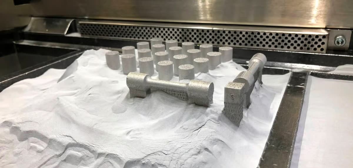
SLS earns its place in the production toolkit because of what the powder bed enables: design freedom without the support-removal tax, part-nesting economics that push print-hour cost down as the bed fills, and mechanical properties close enough to injection-molded nylon to validate assemblies. The same process also imposes real constraints. The surface is grainy out of the machine; parts are a few percent porous and will wick dyes, oils, and finger grease unless sealed; and powder handling introduces a contamination risk that FDM and SLA simply do not have.
| Strength | Cost / Caveat | Engineering implication |
|---|---|---|
| No support-removal geometry constraints | Trapped powder in deep cavities must be evacuated | Design escape holes of ≥ 4 mm for any enclosed volume |
| Functional mechanical properties out of the box | Parts are 5–8% porous | Seal or dye if the part meets fluids, skin, or cosmetic scrutiny |
| Part nesting lowers unit cost as volume fills the bed | Heat history varies across the build chamber | Critical-tolerance features should sit in the bed's sweet spot |
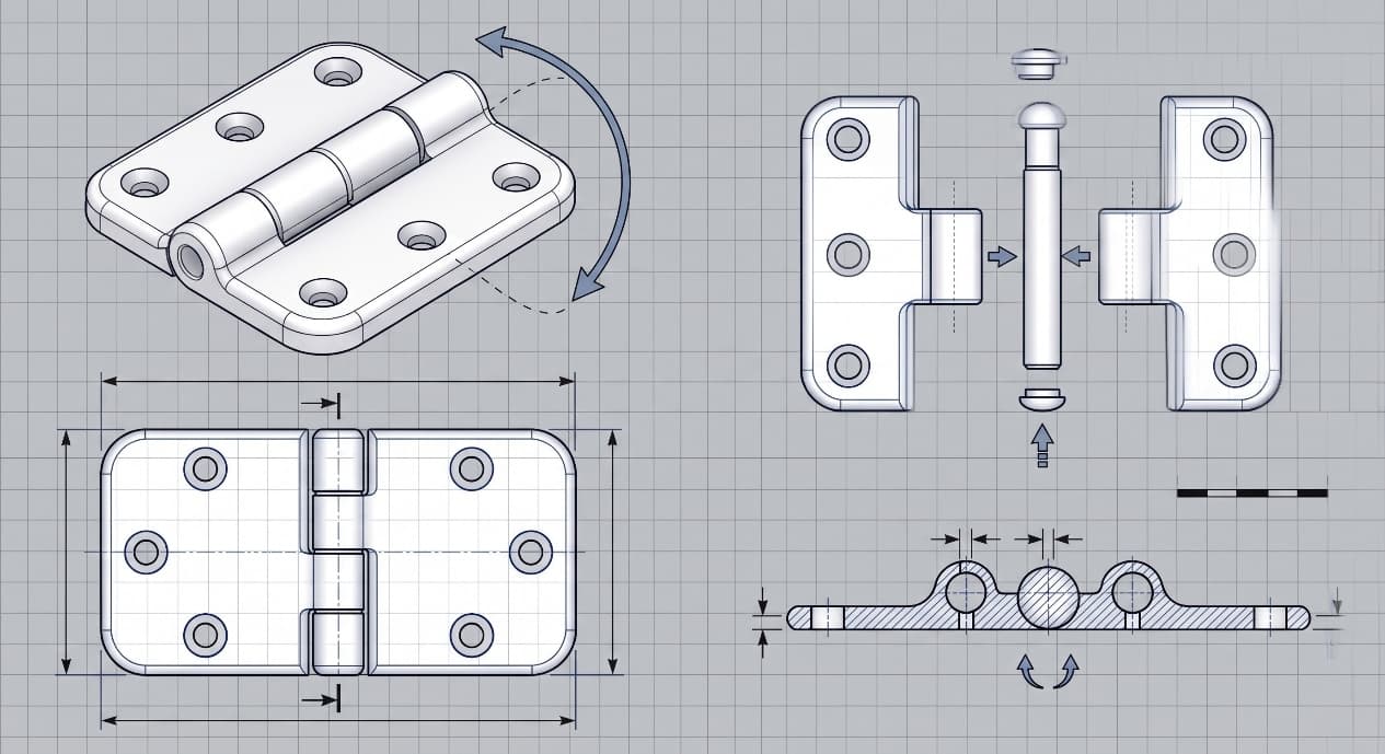
| Living hinges and print-in-place assemblies are routine | Handling can contaminate the surface with powder fines | Plan bead-blast before shipping; build 24-h finishing buffer into lead time |
| Wide material family — from elastomers to glass-filled composites | Elongation drops sharply with filler content | Match family to dominant load mode, not only to datasheet tensile |
SLS vs. MJF — Why the Distinction Matters
SLS and MJF are frequently quoted in the same breath, and for some parts they are interchangeable. They are not the same process. SLS fuses powder with a laser that traces each layer; MJF jets a fusing agent onto a powder bed and then passes an infrared lamp to melt the agent-marked regions.
3D Printing: define requirements before selecting a process
Connect requirements, process decisions and inspection before the first build to reduce late design changes.
- 1Requirements
Function, service environment, quantity and failure risk
- 2Material and process
Material grade, build strategy, geometry and finishing
- 3Inspection
Critical dimensions, functional tests and lot records
Key design rules
Glass-Filled PA12 (PA12 GF) — Stiffness and Dimensional Stability
Loading PA12 with roughly 40% glass beads nearly doubles the modulus, pushes heat-deflection temperature up, and markedly reduces warpage on large flat parts. It is the go-to for jigs, fixtures, structural brackets, and housings that must hold shape under load or heat. The price of that stiffness is impact resistance and elongation: glass-filled nylon is brittle in the thin sections where unfilled PA12 would deform, and a 0.
Polypropylene (PP) — Chemical Resistance and Fatigue
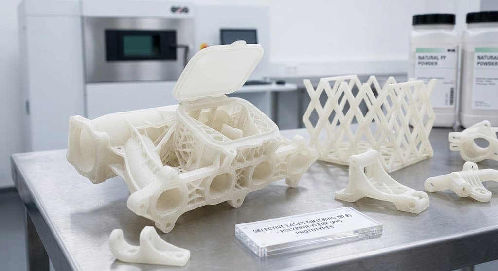
SLS polypropylene is the answer when the part meets acids, solvents, fuels, or repeated-bend fatigue that would crack a nylon hinge. It is softer and weaker than PA12 on a pure tensile basis (roughly 18 MPa against 48 MPa), but it absorbs almost no water — so its dimensions and mechanics are stable in humid or submerged service — and it handles repeated flexing better than any nylon. Typical applications are fluid-handling fittings, closures, chemical-resistant shrouds, nozzles, and living-hinge closures that cycle tens of thousands of times.
| Feature | Recommended minimum (PA12) | Note |
|---|---|---|
| Structural wall | 1.0 mm | 0.7 mm possible for short spans; expect warpage above 100 mm |
| Supported rib / boss | 0.8 mm | Keep aspect ratio below 8:1 to avoid curl |
| Embossed text / detail | 0.5 mm wide × 0.8 mm tall | Sans-serif fonts read cleaner |
| Hole diameter | 1.5 mm | Expect ~0.1 mm undersize; ream critical holes |
| Clearance between moving parts | 0.4–0.5 mm | 0.4 mm is the practical lower bound; 0.6 mm survives dyeing and blasting |
| Powder-escape hole | ≥ 4 mm | Two holes preferred — one for blow-out, one for vent |
From prototyping and finishing to acceptance
Secondary Operations That Make or Break Cosmetic Use
A raw SLS surface is functional but rarely customer-ready. Every part at least receives bead blasting to remove loose powder and even out texture; beyond that baseline, the finishing route depends on what the surface has to do. Vapour smoothing reduces Ra by roughly 70–80% and seals near-surface porosity, which is what makes the part watertight and colour-stable.
| Operation | What it changes | Cost impact | Typical use |
|---|---|---|---|
| Bead blasting | Removes loose powder, evens matte texture | Included in baseline | Every part |
| Vapour smoothing | Ra drops ~70–80%; near-surface porosity sealed | +30–60% over baseline | Watertight housings, cosmetic grips, medical contact surfaces |
| Dyeing | Surface colour to ~0.3–0.5 mm depth | +10–20% | Uniform colour on white-powder parts; functional identification |
| Primer + paint | Full colour control, scratch cover, UV barrier | +40–100% | Consumer-facing cosmetic parts, outdoor exposure |
| Ceramic-like coating | Hardness, heat and chemical resistance | +200–400% | Harsh service — chemical contact, wear interfaces |
3D Printing: four checks before RFQ
- Function
State what the part must do and where it will be used
- Material and process
Name the required grade or performance range
- Design controls
Mark critical geometry, orientation and finishing
- Acceptance
Define dimensions, tests and required records
Pre-RFQ review: recommended practice and common mistakes
| Recommended practice | Common mistake |
|---|---|
| Choose the family by dominant load mode first | Pick by tensile strength alone |
| Use PA11 for any feature that cycles or flexes | Use PA12 for living hinges in high-cycle service |
| Add powder-escape holes on every internal cavity | Ship a closed hollow — it will leak powder for months |
| Budget time for bead blasting on every part | Assume the as-printed surface is customer-ready |
| Dye if you need uniform colour on white-powder parts | Dye a part that will be scratched in service |
| Vapour-smooth anything that must be sealed or touched | Skip sealing on parts that contact skin or sweat |
- Dominant load mode defined: stiffness-driven, ductility-driven, or compliant?
- Temperature and chemical exposure window written on the drawing.
- Living-feature cycle count estimated (and PA11 specified if > 10,000 cycles).
- Powder-escape path reviewed for every enclosed volume.
- Bed-location plan for large flat or precision features.
FAQ, further reading and sources
What should you define first for 3D Printing?
Define the operating environment, functional load, quantity and acceptance criteria before choosing a process. Those requirements determine the material, design rules and inspection plan.
Can the typical values in this guide be released directly on a drawing?
No. Use them for early design, then confirm the exact grade, supplier capability, DFM response and first-article result.
What should be locked before scaling production?
Lock the material, process settings, orientation, finishing and inspection method. Confirm that different lots reproduce the first-article result before scaling.
Next, explore 3D printing services, materials, online quoting, and the related design guides linked below.