How to Design 3D-Printed Hinges That Survive 100k+ Cycles
Content in this Article
3D Printing can look straightforward in CAD and still fail after printing, finishing or inspection. The useful question is not whether a process can make the geometry once, but whether the chosen material, orientation and acceptance method can deliver the required function repeatedly. This guide turns that decision into a practical review workflow.
- Define the operating environment, functional load, quantity and acceptance criteria before choosing a process.
- Treat dimensions and performance values as design-starting points; confirm the exact grade and supplier capability before release.
- Use a first article or pilot lot to lock inspection and process controls before scaling.
Start with requirements and process selection
Why Printed Hinges Fail More Often Than Machined Ones
Machined hinges rely on homogeneous bulk material and tight pin fits. Printed hinges rely on anisotropic layers, process-dependent clearances, and geometry that has to survive powder removal or support removal.
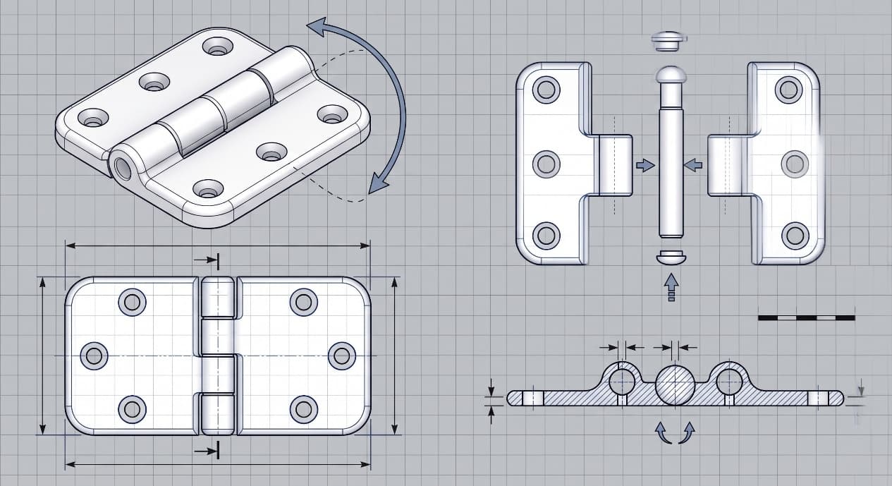
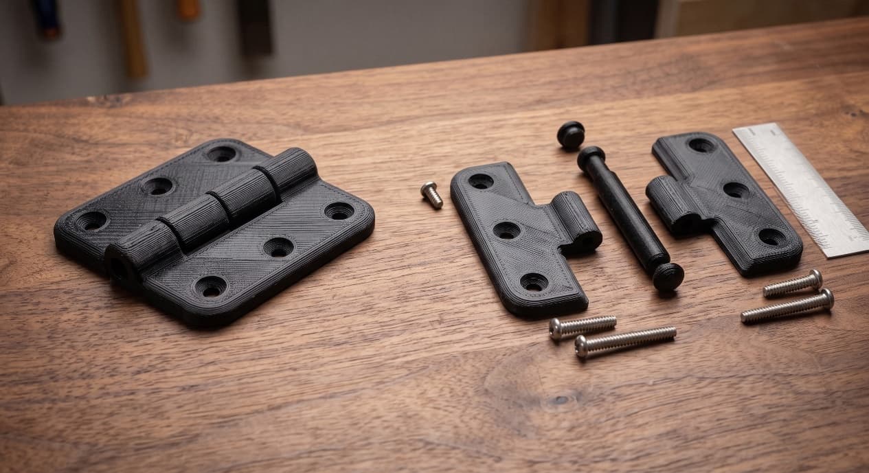
Before geometry, pick the hinge family. Each family has a different life expectancy, a different tolerance budget, and a different assembly story.
Five Hinge Families and When Each Wins
| Hinge Family | Cycle Life (typical) | Best Process | Primary Use |
|---|---|---|---|
| Living hinge (thin flex web) | 50k–200k | MJF / SLS with PA11 | Flip covers, integrated lids |
| Pin-based (two halves + axle) | 100k+ | SLS, FDM, SLA | Doors, panels, repeatable assemblies |
| Snap-with-catch | 1k–10k | SLA, MJF | One-time or low-cycle access covers |
| Knuckle (multi-leaf, printed pin) | 20k–80k | SLS (print-in-place) | Articulated prototypes, mock-ups |
3D Printing: define requirements before selecting a process
Connect requirements, process decisions and inspection before the first build to reduce late design changes.
- 1Requirements
Function, service environment, quantity and failure risk
- 2Material and process
Material grade, build strategy, geometry and finishing
- 3Inspection
Critical dimensions, functional tests and lot records
Key design rules
Geometry Numbers You Can Put on the Drawing
These numbers are the starting point for PA11 living hinges and SLS pin-based hinges. Treat them as defaults, then adjust with prototype data.
| Parameter | Living Hinge (PA11) | Pin-Based (SLS) | Why It Matters |
|---|---|---|---|
| Beam / web thickness | 1.0–1.5 mm | n/a | Below 1.0 mm cracks early; above 1.5 mm resists bending |
| Root radius | 1.5 × beam thickness | 0.5 mm min | Sharp roots concentrate stress and halve cycle life |
| Engagement / leaf length | 5–8 mm | 8–12 mm per knuckle | Too short bends unevenly; too long adds friction |
| Aspect ratio (length : thickness) | 4:1 to 6:1 | 6:1 to 10:1 | Controls bending mode and tear initiation |
Print Orientation Decides Whether Layers Help or Hurt
Same geometry, two orientations, two different products. In one SLS validation build we placed the fold line parallel to the build layers and saw delamination at 2,100 cycles.
From prototyping and finishing to acceptance
3D Printing: four checks before RFQ
- Function
State what the part must do and where it will be used
- Material and process
Name the required grade or performance range
- Design controls
Mark critical geometry, orientation and finishing
- Acceptance
Define dimensions, tests and required records
Pre-RFQ review: recommended practice and common mistakes
| Recommended practice | Common mistake |
|---|---|
| Use PA11 for living hinges whenever MJF/SLS is available | Use PA12 for any hinge above 5,000 cycles |
| Set root radius = 1.5 × beam thickness | Leave sharp internal corners at the fold |
| Orient the fold so layers cross the bend axis | Print the fold parallel to the build plane |
| Specify pin-to-bore clearance 0.3–0.5 mm for SLS | Copy injection-mould clearances into SLS drawings |
- Hinge family chosen against the five-family table before any CAD detail
- Material matches target cycle count from the PA11/PA12/PP/TPU/SLA table
- Beam thickness 1.0–1.5 mm for PA11 living hinges; root radius = 1.5 × thickness
- Engagement length 5–8 mm (living) or 8–12 mm per knuckle (pin)
- Pin-to-bore clearance 0.3–0.5 mm for SLS, 0.4 mm for print-in-place
FAQ, further reading and sources
What should you define first for 3D Printing?
Define the operating environment, functional load, quantity and acceptance criteria before choosing a process. Those requirements determine the material, design rules and inspection plan.
Can the typical values in this guide be released directly on a drawing?
No. Use them for early design, then confirm the exact grade, supplier capability, DFM response and first-article result.
What should be locked before scaling production?
Lock the material, process settings, orientation, finishing and inspection method. Confirm that different lots reproduce the first-article result before scaling.
Next, explore 3D printing services, materials, online quoting, and the related design guides linked below.