Designing Functional Parts for HP Multi Jet Fusion in 2026
Content in this Article
3D Printing can look straightforward in CAD and still fail after printing, finishing or inspection. The useful question is not whether a process can make the geometry once, but whether the chosen material, orientation and acceptance method can deliver the required function repeatedly. This guide turns that decision into a practical review workflow.
- Define the operating environment, functional load, quantity and acceptance criteria before choosing a process.
- Treat dimensions and performance values as design-starting points; confirm the exact grade and supplier capability before release.
- Use a first article or pilot lot to lock inspection and process controls before scaling.

Start with requirements and process selection
MJF Fusing-Agent Physics vs Laser-Sintered SLS
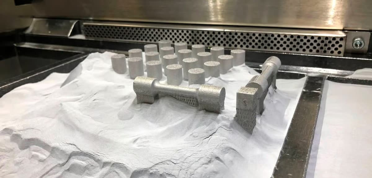
MJF jets a carbon-rich fusing agent only where the part should solidify, then sweeps an infrared lamp across the entire layer. The agent absorbs IR and melts the surrounding PA12 within milliseconds, while a detailing agent at the part edge cools the boundary and sharpens it.
| Metric | HP MJF PA12 | Typical SLS PA12 | Why it matters |
|---|---|---|---|
| Part density | 1.01 g/cm³ | 0.90–0.95 g/cm³ | Higher strength, lower leak path |
| Residual porosity | ~6.8% | ~7.9% | Fewer microvoids, better fatigue |
| Tensile XY / Z | 48 / 48 MPa | 48 / 42 MPa | Near-isotropic, orientation-free |
| Unblasted Ra | ~11 µm | ~15 µm | Skin feels smoother out of bed |
| Native colour | Natural grey | Off-white | Hides cosmetic marks |
The MJF Material Palette You Can Actually Buy in 2026
Process choice is only half the decision — material choice locks in your environmental, electrical, and flammability behaviour. The following families are all qualified on HP Jet Fusion 5200-class hardware and routinely ship in volume today.
3D Printing: define requirements before selecting a process
Connect requirements, process decisions and inspection before the first build to reduce late design changes.
- 1Requirements
Function, service environment, quantity and failure risk
- 2Material and process
Material grade, build strategy, geometry and finishing
- 3Inspection
Critical dimensions, functional tests and lot records
Key design rules
Post-Processing: What the Grey Skin Can Become
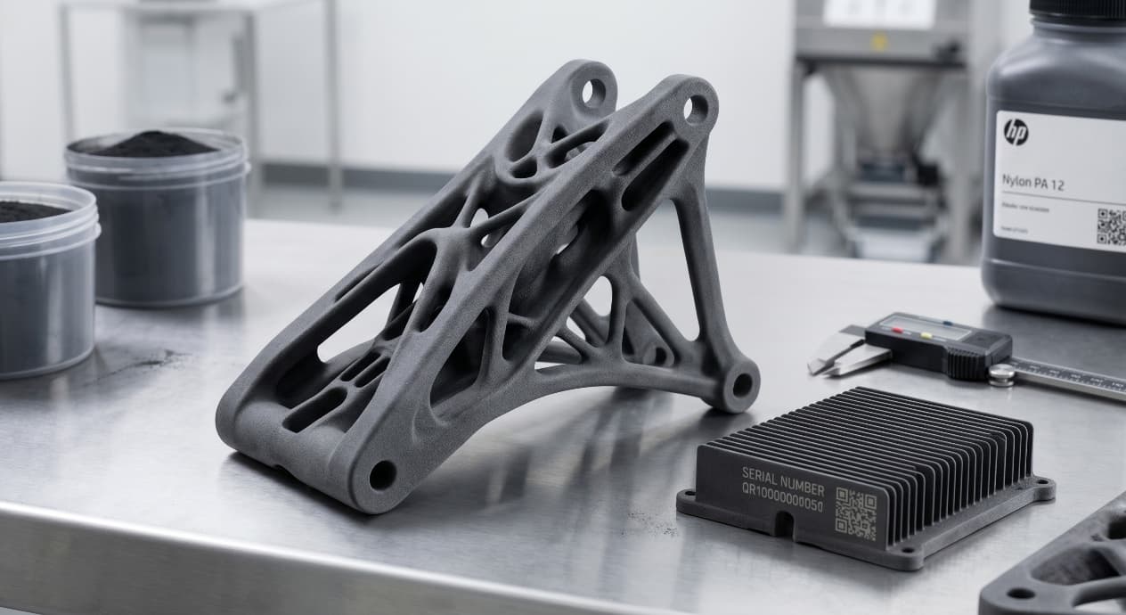
The natural MJF surface is dark grey and slightly chalky because residual fusing agent remains on the skin. Bead-blasting removes that chalk and is the baseline finish for almost every shipped part.
| Finish | Process | Visual | Best use |
|---|---|---|---|
| Standard blast | Glass bead 15–25 s | Matte dark grey | Default for fit & function |
| Dyed black | Vapour / immersion dye | Saturated jet black | Consumer housings |
| Vapour-smoothed | PostPro / AMT chemical | Glossy, Ra < 2 µm | Sealing surfaces, medical |
| Graphite rub | Hand-rubbed graphite | Gunmetal sheen | Short-run aesthetic covers |
| Conductive coat | Ni-Cu spray, 25 µm | Silver, 60 dB shield | EMI / ESD housings |
Why MJF Wins Economically Between 50 and 2,000 Units
A full HP 5200 build envelope is 380 × 284 × 380 mm. Because unfused powder supports every layer, nesting density typically reaches 10–12% by volume — roughly 3× what SLS achieves on equivalent geometry.
From prototyping and finishing to acceptance
Common Mistakes We Still See in 2026
| Mistake | Result | Fix |
|---|---|---|
| Uniform 3 mm wall across whole part | Sink marks, 12-hour cool | Shell to 1.5 mm + ribs |
| Ignoring 1.3% PA12 moisture gain | Hole shrinks 0.1 mm after a week | Bake or coat critical bores |
| Specifying glossy white | Not available on MJF | Pick dyed black or vapour-smooth |
| Nesting tall thin parts vertically | Z warping, blast damage | Lay flat or tilt 15° |
| Using PA12 FR for outdoor UV | FR additive degrades in UV | Switch to PA11 + UV paint |
3D Printing: four checks before RFQ
- Function
State what the part must do and where it will be used
- Material and process
Name the required grade or performance range
- Design controls
Mark critical geometry, orientation and finishing
- Acceptance
Define dimensions, tests and required records
Pre-RFQ review: recommended practice and common mistakes
| Recommended practice | Common mistake |
|---|---|
| Design 1.0 mm walls as your default | Copy SLA 0.6 mm wall values |
| Add a 4 mm powder-escape per closed cavity | Seal internal lattices with no exit |
| Orient snap-fits so load is across XY | Stack cantilevers along Z |
| Quote bead-blast as baseline finish | Assume paint-ready skin out of bed |
| Use PA11 when elongation > 25% is needed | Default every project to PA12 |
- All walls ≥ 1.0 mm and shelled where possible
- Every closed cavity has at least one 4 mm powder-escape hole
- Moving clearances set to 0.4 mm (0.5 mm for PA11)
- Critical bores called out with +0.2 mm machining stock
- Snap-fits oriented so flex is in XY, not along Z
FAQ, further reading and sources
What should you define first for 3D Printing?
Define the operating environment, functional load, quantity and acceptance criteria before choosing a process. Those requirements determine the material, design rules and inspection plan.
Can the typical values in this guide be released directly on a drawing?
No. Use them for early design, then confirm the exact grade, supplier capability, DFM response and first-article result.
What should be locked before scaling production?
Lock the material, process settings, orientation, finishing and inspection method. Confirm that different lots reproduce the first-article result before scaling.
Next, explore 3D printing services, materials, online quoting, and the related design guides linked below.