Designing for Stereolithography: Walls, Supports, Drainage, and Post-Cure
Content in this Article
3D Printing can look straightforward in CAD and still fail after printing, finishing or inspection. The useful question is not whether a process can make the geometry once, but whether the chosen material, orientation and acceptance method can deliver the required function repeatedly. This guide turns that decision into a practical review workflow.
- Define the operating environment, functional load, quantity and acceptance criteria before choosing a process.
- Treat dimensions and performance values as design-starting points; confirm the exact grade and supplier capability before release.
- Use a first article or pilot lot to lock inspection and process controls before scaling.
Start with requirements and process selection
Why SLA Design Is Different from FDM Design
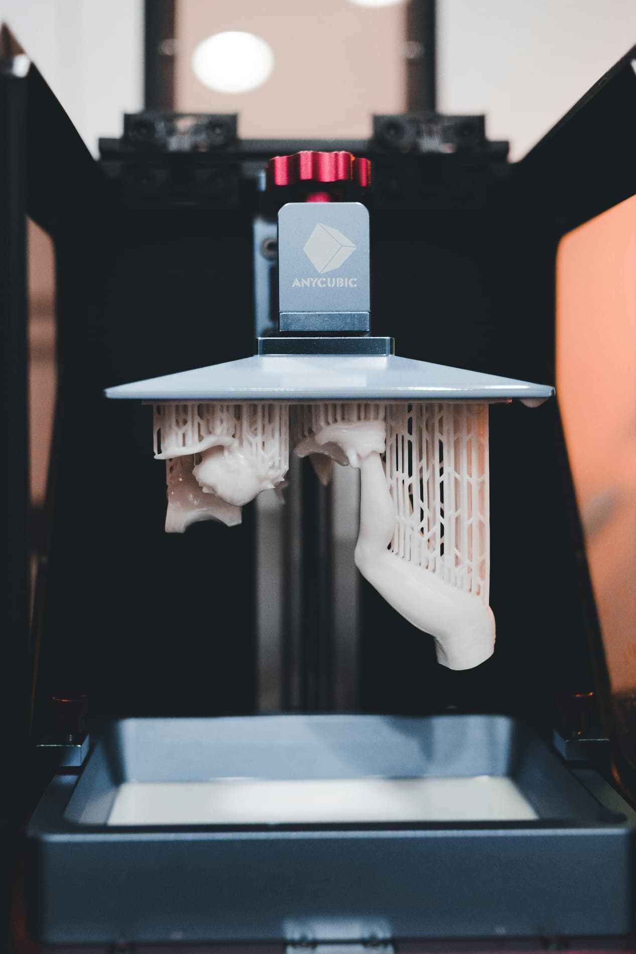
FDM is an extrusion process: gravity, bridging, and Z-seam are the dominant constraints. SLA is a peel process: every layer is pulled away from a film or vat floor, and that peel force scales with the cross-sectional area exposed in that slice. A wide, flat layer parallel to the build plate sees the highest peel force; a part oriented on edge sees almost none.
The corollary is that SLA design is inseparable from print orientation. You cannot finalize a feature spec without deciding how the part will sit in the vat, because that decision changes which faces are support-scarred, which cavities trap resin, and which axis carries the worst dimensional error. Treat orientation as a design input, not a slicer afterthought.
SLA-Specific DFM Limits
The numbers below are conservative defaults for general-purpose engineering resins on a desktop or benchtop SLA system with a 50 to 100 micron laser spot or pixel. Tough, flexible, and high-temperature resins typically need 20% to 40% more thickness; ceramic-filled and castable resins need more support density. 關鍵設計動作: lock orientation first, then validate every wall, hole, and overhang against the orientation, not against the CAD axes.
| Feature | Minimum | Recommended | Why It Fails Below Minimum |
|---|---|---|---|
| Unsupported wall | 0.5 mm | 0.8 to 1.2 mm | Peel force tears the wall off the supports mid-build |
| Supported wall | 0.4 mm | 0.6 mm | Wall flexes during recoat, prints with wave |
| Through-hole diameter | 0.5 mm (vertical) | 1.0 mm | Uncured resin clogs the hole and cures shut in post-cure |
| Embossed text height | 0.4 mm | 0.6 mm | Letters print but lose definition after post-cure swell |
| Engraved text depth | 0.4 mm | 0.6 mm | Resin pools in the recess, infills the letterform |
| Unsupported overhang | 30 deg from vertical | 45 deg | Layers droop under weight before next layer locks them |
3D Printing: define requirements before selecting a process
Connect requirements, process decisions and inspection before the first build to reduce late design changes.
- 1Requirements
Function, service environment, quantity and failure risk
- 2Material and process
Material grade, build strategy, geometry and finishing
- 3Inspection
Critical dimensions, functional tests and lot records
Key design rules
Drainage Strategy for Hollowed Bodies
Hollowing a part to save resin is standard practice, but a sealed hollow is a trap. Uncured resin inside a closed shell does not stop being photoreactive; UV passing through a thin wall during post-cure will partially solidify the trapped pool, and the resulting shrinkage will deform or crack the shell. Every hollow needs at least one drain hole, and ideally two — an inlet at the lowest point in print orientation and a vent at the highest.
| Hollow Volume | Single Drain Hole | Two-Hole (Inlet+Vent) | Notes |
|---|---|---|---|
| < 5 cm3 | 3 mm | Optional | Centrifuge or shake out |
| 5 to 30 cm3 | 4 mm | Recommended 3 mm + 3 mm | IPA flush via inlet |
| 30 to 100 cm3 | 5 mm | Required 4 mm + 4 mm | Negative pressure recommended |
| > 100 cm3 | 6 mm | Required 5 mm + 5 mm | Consider segmenting and bonding |
Designing for Post-Cure Dimensional Shift
Green parts coming off an SLA platform are 80% to 95% cured. The remaining cure happens during a UV bath at 40 to 60 deg C, and the part shrinks during that step. Typical shrinkage ranges from 0.
Holes shrink inward, bosses shrink outward, and slot widths shrink toward the centerline. If your part has a press-fit bore for a metal pin, draw it 0. 4% larger than nominal in the orientation it will print.
From prototyping and finishing to acceptance
3D Printing: four checks before RFQ
- Function
State what the part must do and where it will be used
- Material and process
Name the required grade or performance range
- Design controls
Mark critical geometry, orientation and finishing
- Acceptance
Define dimensions, tests and required records
Pre-RFQ review: recommended practice and common mistakes
| Recommended practice | Common mistake |
|---|---|
| Decide print orientation before locking feature dimensions | Hand the slicer a CAD model and ask it to figure orientation out |
| Add at least one 3 mm drain hole to every hollow | Hollow a body and seal it because the outer surface looks better |
| Compensate bores by 0.3% to 0.6% in the print direction | Print a press fit at nominal CAD and hope post-cure cooperates |
| Hide support scars on a designated B-side surface | Place the most cosmetic face downward on the build plate |
| Choose the resin family before finalizing wall thicknesses | Design to standard resin then swap to tough or flexible later |
| Tilt thin walls 15 to 30 degrees off vertical | Print thin walls perfectly flat to the build plate |
- Orientation locked and B-side identified before slicing
- All unsupported walls at or above 0.5 mm in print direction
- Every hollow has a drain hole sized to its volume (3 to 6 mm)
- Overhangs above 30 degrees from vertical or supported
- Bores compensated for post-cure shrinkage in the print axis
FAQ, further reading and sources
What should you define first for 3D Printing?
Define the operating environment, functional load, quantity and acceptance criteria before choosing a process. Those requirements determine the material, design rules and inspection plan.
Can the typical values in this guide be released directly on a drawing?
No. Use them for early design, then confirm the exact grade, supplier capability, DFM response and first-article result.
What should be locked before scaling production?
Lock the material, process settings, orientation, finishing and inspection method. Confirm that different lots reproduce the first-article result before scaling.
Next, explore 3D printing services, materials, online quoting, and the related design guides linked below.