Designing for Powder Bed Fusion: Variants, DFM, and Depowdering
Content in this Article
3D Printing can look straightforward in CAD and still fail after printing, finishing or inspection. The useful question is not whether a process can make the geometry once, but whether the chosen material, orientation and acceptance method can deliver the required function repeatedly. This guide turns that decision into a practical review workflow.
- Define the operating environment, functional load, quantity and acceptance criteria before choosing a process.
- Treat dimensions and performance values as design-starting points; confirm the exact grade and supplier capability before release.
- Use a first article or pilot lot to lock inspection and process controls before scaling.
Start with requirements and process selection
The PBF Family at a Glance
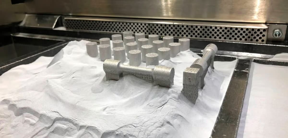
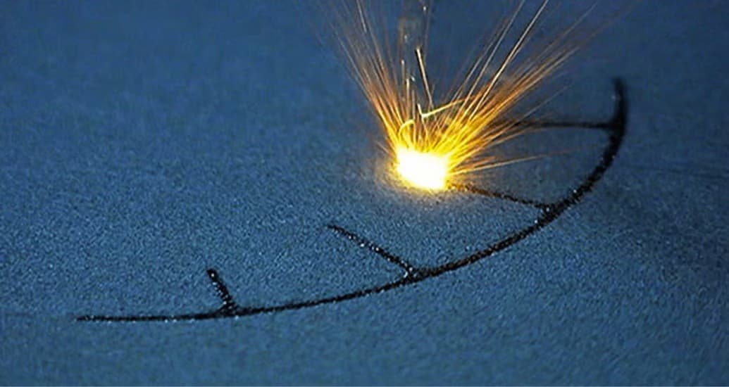
PBF covers every process that fuses powder inside a heated bed. On the polymer side that means SLS (laser), MJF (infrared + fusing agent), and SBJ-style variants. On the metal side it covers DMLS and SLM (fibre laser), EBM (electron beam), and increasingly green-laser copper systems.
The variant decides almost everything else: how the layer is drawn, how much residual stress accumulates, whether supports are needed, how powder is recovered, and how much the part will shrink or distort. Picking the wrong variant for the geometry is still the most common root cause of a PBF part missing spec on first build.
| Variant | Energy | Typical Materials | Supports Needed | Primary Use |
|---|---|---|---|---|
| SLS | CO2 or fibre laser | PA12, PA11, PA-GF, TPU | No (powder only) | Functional polymer parts |
| MJF | IR + fusing agent | PA12, PA11, PP, TPU | No | Production polymer parts |
| DMLS/SLM | Fibre laser | 17-4PH, Ti6Al4V, AlSi10Mg, Inconel | Yes (anchors + thermal) | Dense metal parts |
| EBM | Electron beam | Ti6Al4V, CoCr | Partial (sintered cake) | Medical, aerospace titanium |
| Green-laser LPBF | Green fibre laser | Pure Cu, CuCrZr | Yes | Heat exchangers, induction coils |
Build Volumes and Layer Thickness
Build volume sets the part-packing economics. Layer thickness sets the surface and the z-axis resolution. Getting those two numbers right up front stops the common pattern where a part is designed to a nominal wall, then discovered to lose features when it is actually sliced at the real layer thickness the service bureau uses.
3D Printing: define requirements before selecting a process
Connect requirements, process decisions and inspection before the first build to reduce late design changes.
- 1Requirements
Function, service environment, quantity and failure risk
- 2Material and process
Material grade, build strategy, geometry and finishing
- 3Inspection
Critical dimensions, functional tests and lot records
Key design rules
DFM Numbers You Can Actually Design To
These numbers are not vendor marketing — they are what most production shops will accept without escalating the part for review. Staying inside these bounds keeps the first build usable. Pushing beyond them is possible but should be a conscious choice with a DFM discussion, not an accidental CAD default.
| Feature | SLS/MJF (PA12) | DMLS (Metal) | Comment |
|---|---|---|---|
| Min wall | 0.8 mm | 0.4 mm | Thinner walls warp |
| Min clearance (assembled) | 0.4 mm | 0.2 mm | Per side, fused state |
| Min hole diameter | 0.5 mm | 0.3 mm | Plus depth ratio |
| Min overhang (self-supporting) | N/A | 45° from build plate | Below needs supports |
| Powder-escape hole | Ø4 mm | Ø3 mm | Per enclosed volume |
| Max unsupported bridge | N/A | 2 mm | Then sags or curls |
Why PBF Enables Geometry Others Cannot
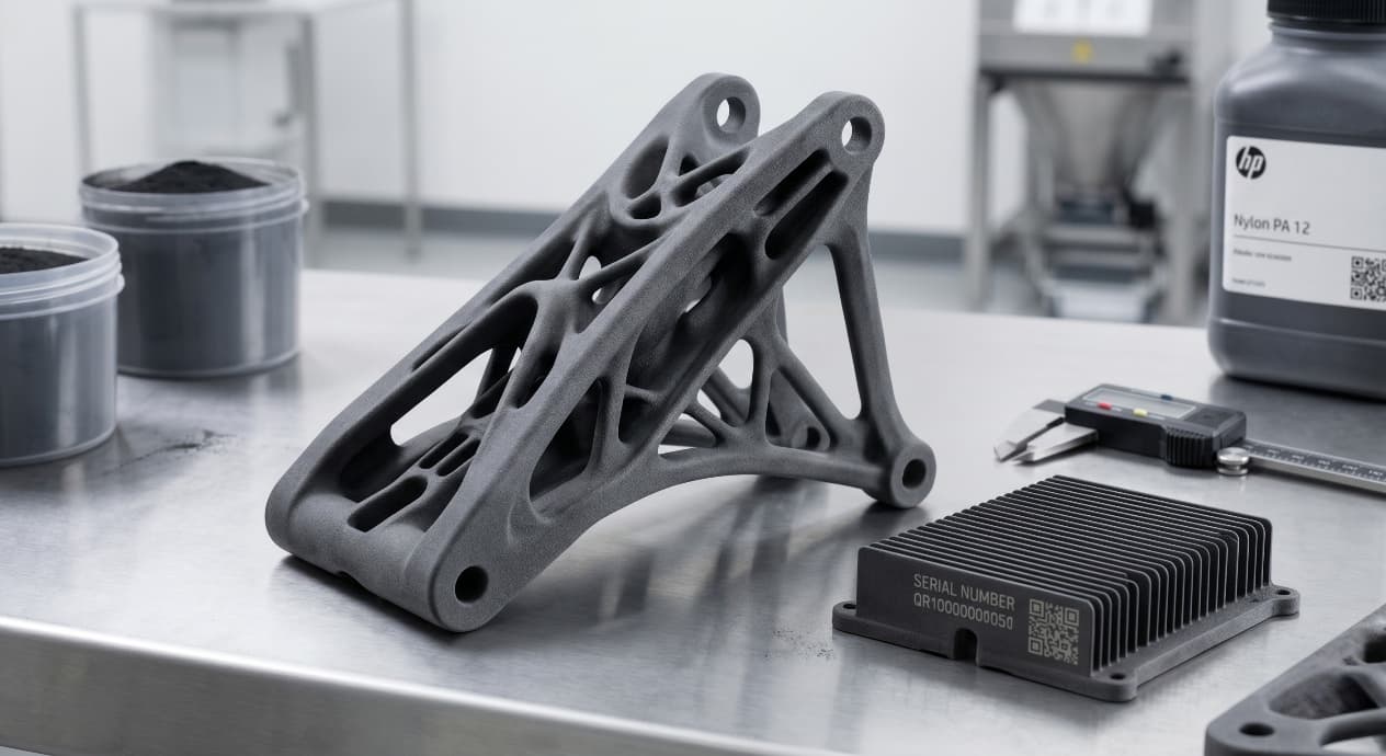
Polymer PBF is support-free because the surrounding cake holds the part through the build. That single fact is why MJF and SLS dominate low-volume end-use nylon hardware: the part comes out clean without witness marks, and designers can stack 300+ parts per build without a scaffold forest.
Metal PBF is not support-free. The dense molten pool shrinks and pulls against the build plate, so anchors and thermal-conduction supports are still needed below roughly 45 degrees. What metal PBF does offer is consolidated assemblies — a rocket injector that used to be 250 machined and brazed parts can ship as a single LPBF print.
| Geometry | Conventional Cost | PBF Cost | Typical Ratio |
|---|---|---|---|
| Conformal cooling insert | High (EDM + brazing) | Medium (DMLS) | PBF ~0.6x |
| Topology-optimized bracket | Very high (5-axis + weld) | Medium (DMLS) | PBF ~0.4x |
| Gyroid heat exchanger | Not feasible | Medium (LPBF) | Only PBF |
| Nested production clips | High (tool + mold) | Low (MJF) | PBF ~0.3x at <2k |
From prototyping and finishing to acceptance
Post-Processing Is Part of the Design
PBF parts rarely leave the build chamber as finished goods. Polymer parts typically go through depowdering, bead blasting, optional dyeing or vapor smoothing, and dimensional check. Metal parts add stress relief on the plate, wire-EDM cutoff, support removal, HIP for fatigue-critical work, heat treatment, CNC of mating surfaces, and CMM or CT inspection.
| Step | Polymer PBF | Metal PBF | Typical Time |
|---|---|---|---|
| Cooldown | 8–24 h | 4–12 h | Passive |
| Depowder | Manual brush + air | Vacuum + brush | 0.5–2 h/part |
| Stress relief | N/A | 600–900°C on plate | 4–8 h |
| Support removal | N/A | Manual + wire EDM | 1–6 h/part |
| Finishing | Bead blast, dye | Blast, tumble, polish | 1–4 h/part |
| Inspection | Caliper, 3D scan | CMM, CT, FPI | Variable |
3D Printing: four checks before RFQ
- Function
State what the part must do and where it will be used
- Material and process
Name the required grade or performance range
- Design controls
Mark critical geometry, orientation and finishing
- Acceptance
Define dimensions, tests and required records
Pre-RFQ review: recommended practice and common mistakes
| Common mistake | Likely outcome | How to improve |
|---|---|---|
| Variant choice | Name SLS/MJF/DMLS/LPBF before locking CAD | Design for 'PBF in general' |
| Wall thickness | Stay at or above 0.8 mm polymer, 0.4 mm metal | Push to machine-theoretical minimum |
| Enclosed volumes | Add a Ø3–4 mm powder-escape hole per cavity | Assume powder will flow around corners |
| Overhangs (metal) | Keep self-supporting at 45° or above | Expect good finish on downskin surfaces |
| Orientation | Align principal stress with XY plane | Leave orientation to the bureau default |
| Finish callouts | Specify Ra range, not 'smooth' | Assume as-built Ra meets functional spec |
- PBF variant named on the drawing (SLS / MJF / DMLS / LPBF / EBM).
- Principal stress axis is in the XY build plane, not along Z.
- Every enclosed volume has at least one Ø3–4 mm powder-escape hole.
- Metal overhangs below 45° have supports shown in the build-prep view.
- Wall thickness is at or above 0.8 mm polymer / 0.4 mm metal minimum.
FAQ, further reading and sources
What should you define first for 3D Printing?
Define the operating environment, functional load, quantity and acceptance criteria before choosing a process. Those requirements determine the material, design rules and inspection plan.
Can the typical values in this guide be released directly on a drawing?
No. Use them for early design, then confirm the exact grade, supplier capability, DFM response and first-article result.
What should be locked before scaling production?
Lock the material, process settings, orientation, finishing and inspection method. Confirm that different lots reproduce the first-article result before scaling.
Next, explore 3D printing services, materials, online quoting, and the related design guides linked below.