What Is 3D Printing in 2026: A Working Engineer's Map
Content in this Article
3D Printing creates value when geometry, volume, revision frequency and functional requirements fit additive manufacturing. This guide connects process, material, design and inspection decisions.
- Define function, environment, quantity and risk before selecting a material or process.
- Treat typical values as comparison points; confirm the exact grade and supplier capability before release.
- Use a first article or pilot lot to verify dimensions, function and records before scaling.
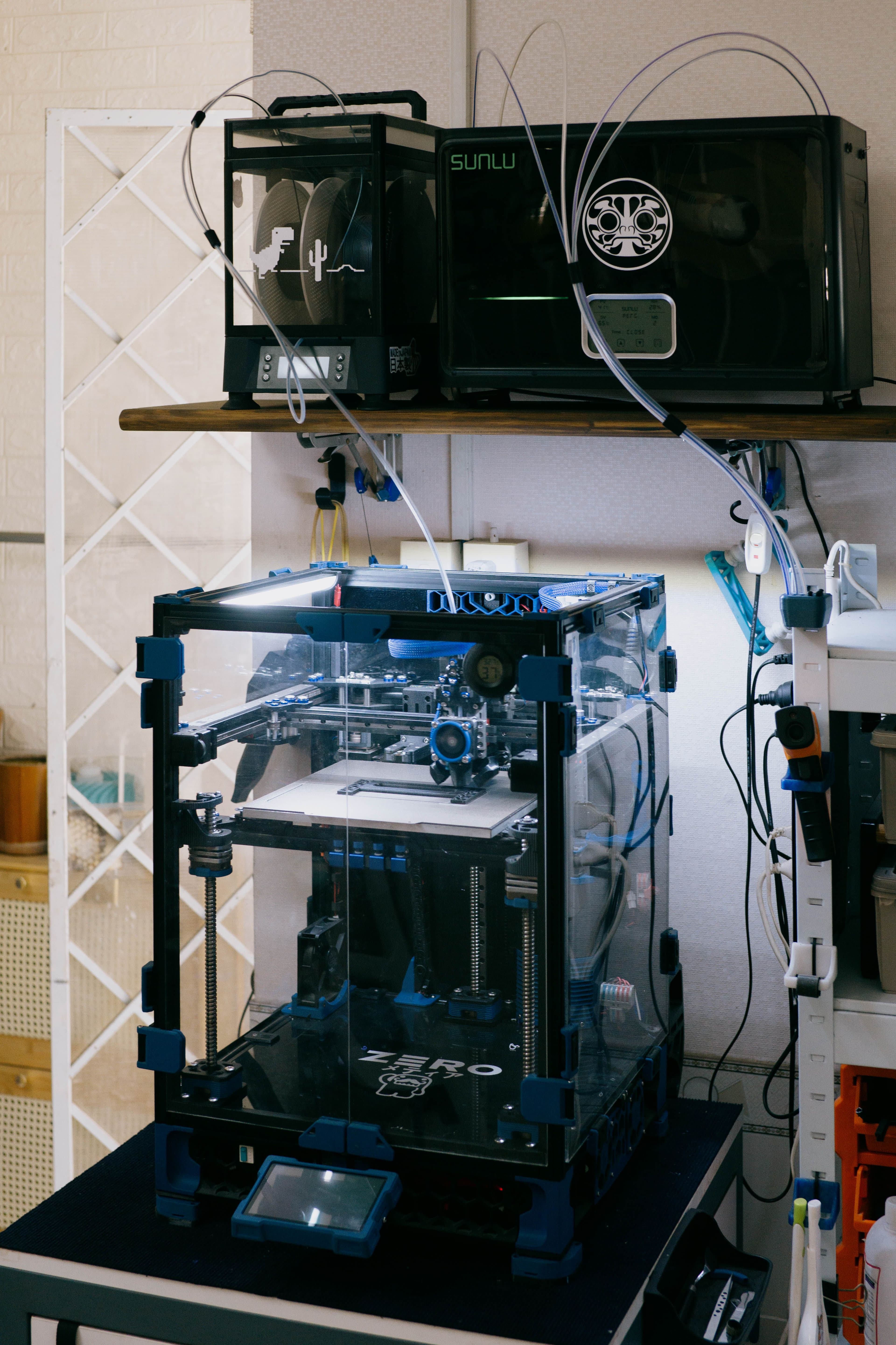
Define the decision
Document function, environment, quantity and risk so every option is compared against the same requirement.
What Actually Happens Inside the Machine
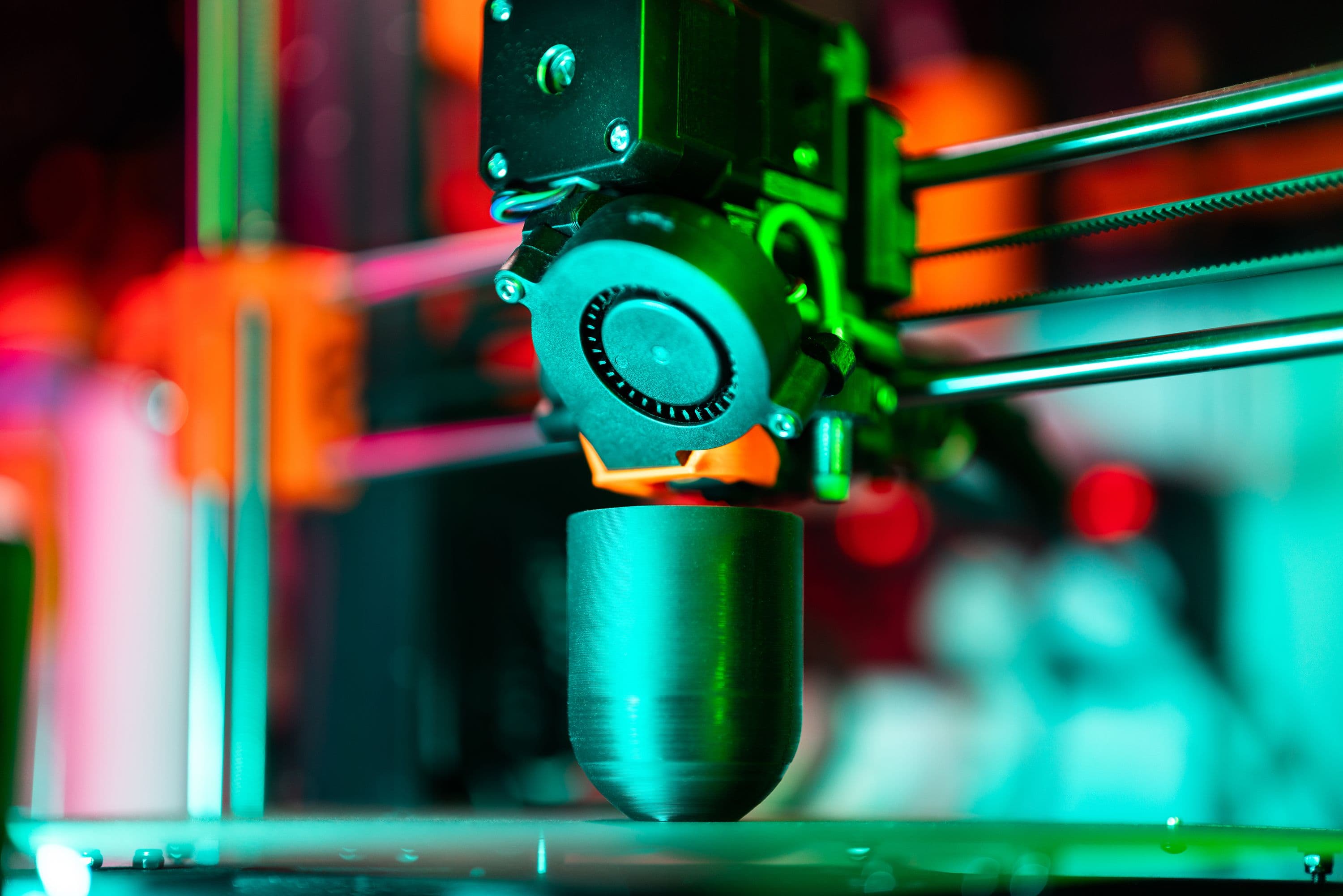
Every additive process follows the same five logical steps — model, slice, print, post-process, inspect — but the physics under the nozzle or laser differ enough that a design decision which helps one process can destroy another. SLA cures liquid photopolymer with UV at 25–100 micron layers.
3D Printing evaluation flow
Define requirements, narrow the material and process, then verify with a consistent acceptance method.
- 1Requirements
Function, environment, quantity and risk
- 2Options
Material, process, design controls and finishing
- 3Acceptance
Dimensions, functional tests and production records
Compare the practical options
Compare material, process, design controls and finishing together—not unit price alone.
Picking a Material Before You Pick a Process
The fastest way to waste a week is to lock in a process and then discover the material it supports will not survive your operating temperature, chemical exposure, or UV load. Start from the load case.
| Load Case | Good Choice | Avoid | Why |
|---|---|---|---|
| Continuous 90 C service | PA12-GF (MJF), PC (FDM) | Standard SLA resin | Resin HDT often 50–60 C |
| Repeated living-hinge flex | PA12 (MJF/SLS) | SLA, PolyJet | Photopolymer fatigue < 500 cycles |
| Transparent optical | Clear SLA, PolyJet VeroClear | MJF, SLS | Powder processes opaque |
| Outdoor UV 12+ months | ASA (FDM), PA11 (MJF) with coat | Raw SLA resin | Yellowing and chalking |
| Medical skin contact | Biocompatible SLA (Class I) | Unrated FDM filament | Regulatory traceability |
Designing for Additive Without Designing Yourself Into a Corner
The most common mistake is importing CNC habits — uniform wall thickness, symmetric features, generous radii — into an additive file. Additive rewards stress-aligned ribs, lattices, and unsupported overhangs up to 45 degrees (polymer) or 35 degrees (metal).
| recommended practice | common mistake |
|---|---|
| Orient the part so critical surfaces face up or sideways | Print cosmetic faces downward on supports |
| Keep polymer walls ≥ 0.8 mm, metal ≥ 0.5 mm | Walls below 0.4 mm on any process |
| Add ≥ 3 mm drain holes in enclosed volumes | Sealed pockets that trap powder or resin |
| Use chamfers instead of horizontal overhangs | Sharp 90° overhangs > 2 mm unsupported |
| Specify Ra finish only on surfaces that need it | Uniform 1.6 Ra everywhere |
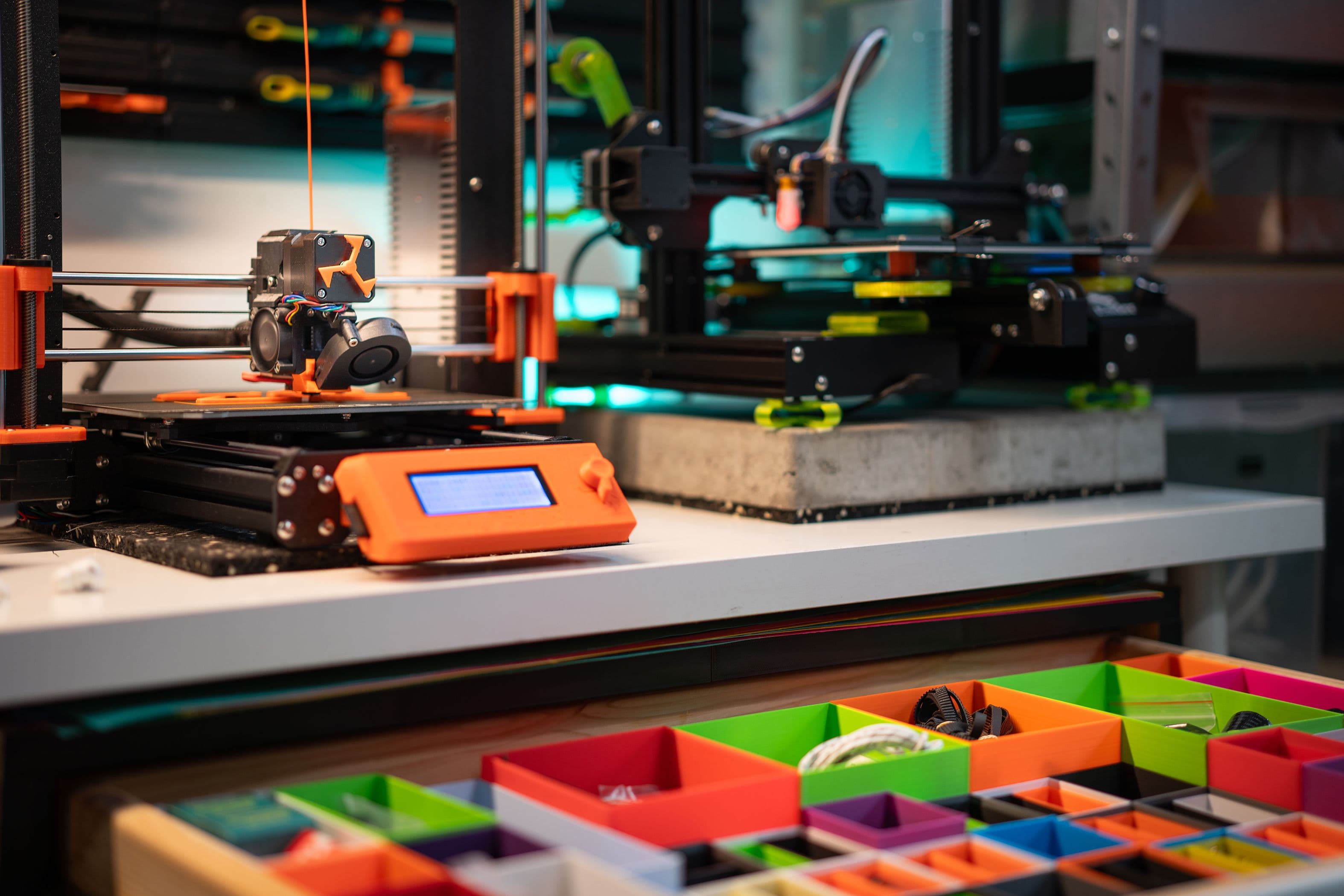
Validate before scaling
Before scaling, verify dimensions, function and records with one controlled method across representative lots.
The Mistakes That Show Up on Every First-Time Additive Review
| Mistake | Why It Fails | How to Avoid |
|---|---|---|
| Treating STL tolerance as ±0.05 mm | Polymer processes hold ±0.2 mm best case | Design mating features with 0.3–0.5 mm clearance |
| Uniform 2.5 mm wall everywhere | Wastes material and build time | Vary 0.8–2.0 mm with stress field |
| No drain holes on closed shells | Trapped PA12 powder 30–80 g per part | Add 3 mm holes at low points |
| Specifying machined thread M3 | SLS threads strip at 4–6 N·m | Use heat-set inserts or tapped hole M4+ |
| Cosmetic class-A on side walls | Build lines visible at 0.12 mm layers | Post-process vapor smoothing or paint |
Matching Industry to Process
| Industry | Dominant Process | Typical Part | Value Driver |
|---|---|---|---|
| Aerospace | DMLS Ti / Inconel | Brackets, fuel nozzles | Mass + part consolidation |
| Medical | SLA + DMLS | Surgical guides, implants | Patient-specific geometry |
| Automotive | MJF + SLS | Interior clips, ducts | < 5,000 unit runs |
| Consumer electronics | MJF + SLA | Housings, bezels | Weekly iteration |
| Industrial | SLS + FDM | Jigs, end-of-arm tools | Lead time days vs weeks |
Pre-RFQ review: recommended practice and common mistakes
| Recommended practice | Common mistake |
|---|---|
| Document function, environment, quantity and risk | Select from a material name or machine specification alone |
| Review material, process, design controls and finishing together | Address manufacturing limits only after design freeze |
| Inspect critical dimensions and function on the first article | Scale production from visual approval alone |
| Keep material, revision and inspection records | Reuse old results after a material or process change |
- Function, environment, quantity and risk are documented
- Material, process, design controls and finishing are reviewed with the supplier
- Critical dimensions, appearance and functional acceptance are on the drawing or RFQ
- First-article or pilot-lot verification is planned
- Material, process and revision changes trigger a new review
FAQ, further reading and sources
What should be defined first for 3D Printing?
Start with function, environment, quantity and acceptance criteria. These inputs narrow the practical options faster than naming a machine or material first.
Can typical values in this article be released directly on a drawing?
No. Use them for early comparison, then confirm the exact grade, supplier capability and first-article result.
When is the process ready to scale?
Scale only after material, process, finishing and inspection are controlled and repeatable across representative lots.
Next, explore 3D printing services, CNC machining, materials, and the related reports linked on this page.