Vapour Smoothing for 3D-Printed Parts — When It Pays Back
Content in this Article
3D Printing can look straightforward in CAD and still fail after printing, finishing or inspection. The useful question is not whether a process can make the geometry once, but whether the chosen material, orientation and acceptance method can deliver the required function repeatedly. This guide turns that decision into a practical review workflow.
- Define the operating environment, functional load, quantity and acceptance criteria before choosing a process.
- Treat dimensions and performance values as design-starting points; confirm the exact grade and supplier capability before release.
- Use a first article or pilot lot to lock inspection and process controls before scaling.

Start with requirements and process selection
What Vapour Smoothing Actually Does
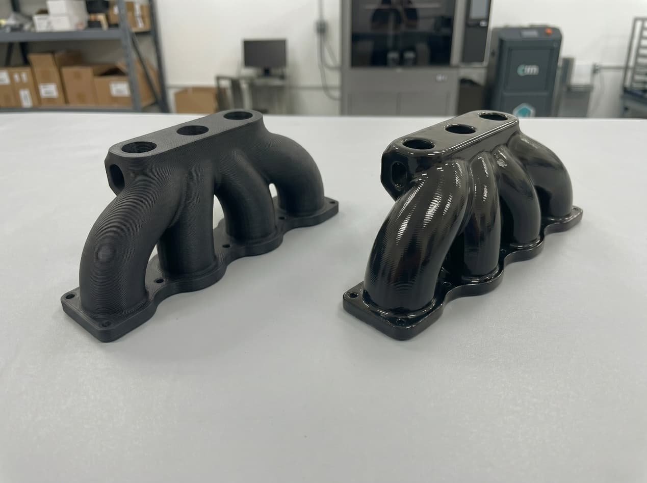
The process exposes the part to a solvent vapour — most commercial systems use a proprietary blend optimised for the target material — inside a sealed chamber. The vapour condenses on the cooler part surface, softens the outer ~20–50 µm of material, and the softened layer flows into the adjacent low points under surface tension before the chamber is purged and the part re-solidifies.
| Effect | Typical magnitude | Why it happens |
|---|---|---|
| Surface roughness reduction | Ra 10–12 µm → Ra 1–3 µm | Softened layer flows into low points under surface tension |
| Dimensional change on external surfaces | +0.05–0.10 mm per surface (net material addition) | Reflowed material deposits slightly beyond original profile |
| Near-surface porosity closure | ~60–80% reduction | Softened layer closes the micro-voids left by powder sintering |
| Watertightness | From IP54 to IPX7-equivalent | Sealed outer skin blocks wicking paths |
Which Materials It Works On, and Which It Doesn't
Vapour smoothing chemistry is material-specific. A cycle tuned for PA12 will not work on TPU; a cycle for ABS will damage PP.
3D Printing: define requirements before selecting a process
Connect requirements, process decisions and inspection before the first build to reduce late design changes.
- 1Requirements
Function, service environment, quantity and failure risk
- 2Material and process
Material grade, build strategy, geometry and finishing
- 3Inspection
Critical dimensions, functional tests and lot records
Key design rules
How Smoothing Shifts Fit and Tolerance
The single most reliable way to wreck a smoothing programme is to specify tolerances on the raw printed dimensions and discover — after finishing — that the fit has closed by 0. 1 to 0.
| Design feature | Uncompensated problem | Fix |
|---|---|---|
| Slip-fit clearance | Closes 0.1–0.2 mm → binds | Add 0.15 mm per mating surface to nominal CAD |
| Press-fit interference | Interference grows 0.1–0.2 mm → cannot assemble | Reduce interference, or mask one surface before smoothing |
| Snap-fit engagement | Beam gets stiffer, engagement travel changes | Re-validate force window on smoothed parts |
| Sealing groove | Groove depth reduces by one smoothing layer | Specify groove dimension in post-smoothed state |
From prototyping and finishing to acceptance
3D Printing: four checks before RFQ
- Function
State what the part must do and where it will be used
- Material and process
Name the required grade or performance range
- Design controls
Mark critical geometry, orientation and finishing
- Acceptance
Define dimensions, tests and required records
Pre-RFQ review: recommended practice and common mistakes
| Recommended practice | Common mistake |
|---|---|
| Compensate CAD clearances for +0.05–0.10 mm per smoothed surface | Tolerance smoothed parts to raw-print dimensions |
| Decide smoothing before freezing fit tolerances | Add smoothing after tolerance sign-off |
| Mask threads, datum faces, and critical seals before smoothing | Smooth threads and expect fasteners to engage |
| Choose materials with smoothing in mind from the start | Pick PP or PEEK and hope smoothing can be retrofitted |
- Material is on the smoothing-compatibility list before the programme freezes material selection.
- CAD clearances are specified in the post-smoothed state and compensated for +0.05–0.10 mm per surface.
- Threads, datum faces, and critical seals are either masked or designed to be machined after smoothing.
- The finish requirement ties to a real use-case need (hygiene / IP rating / tactile / appearance).
- IP rating or watertightness claims are verified on smoothed samples, not raw prints.
FAQ, further reading and sources
What should you define first for 3D Printing?
Define the operating environment, functional load, quantity and acceptance criteria before choosing a process. Those requirements determine the material, design rules and inspection plan.
Can the typical values in this guide be released directly on a drawing?
No. Use them for early design, then confirm the exact grade, supplier capability, DFM response and first-article result.
What should be locked before scaling production?
Lock the material, process settings, orientation, finishing and inspection method. Confirm that different lots reproduce the first-article result before scaling.
Next, explore 3D printing services, materials, online quoting, and the related design guides linked below.