Designing Lattice Structures That Actually Deliver
Content in this Article
3D Printing can look straightforward in CAD and still fail after printing, finishing or inspection. The useful question is not whether a process can make the geometry once, but whether the chosen material, orientation and acceptance method can deliver the required function repeatedly. This guide turns that decision into a practical review workflow.
- Define the operating environment, functional load, quantity and acceptance criteria before choosing a process.
- Treat dimensions and performance values as design-starting points; confirm the exact grade and supplier capability before release.
- Use a first article or pilot lot to lock inspection and process controls before scaling.
Start with requirements and process selection
What a Lattice Is Actually For
The engineering argument for a lattice is always the same: place mass where it carries load and remove it everywhere else. A solid block carries load uniformly because it has mass uniformly. A well-designed lattice keeps the load-carrying geometry and strips the rest.
| Lattice objective | What you are actually buying | Typical density target | Fails if misapplied |
|---|---|---|---|
| Lightweighting | Mass reduction with stiffness preserved in critical zones | 20–40% relative density, graded higher near loads | Weight drops but stiffness collapses; crack at skin-lattice transition |
| Energy absorption | Predictable crush behaviour under impact | 15–25% density, designed to fold progressively | Hard elastic rebound (bounces injuries) instead of absorbing |
| Thermal / airflow | Controlled porous path for cooling or drainage | Open-cell 30–50% density, cell ≥ 3 mm | Trapped powder / resin that blocks the very flow you designed for |
| Stiffness tuning (variable) | Local compliance where a rigid frame is unwanted | 20–80% density, graded by region | Uniform mid-density lattice that matches neither stiff nor soft requirement |
| Bone-analogue / osseointegration | Pore size that supports cell ingrowth | 60–80% porosity, pore 300–800 µm | Too dense → no ingrowth; too porous → mechanical failure |
| Acoustic / vibration damping | Loss-factor lift through internal architecture | Application-specific, usually 30–50% | Designed for weight instead of damping; no damping gain |
Cell Types and Where Each One Wins
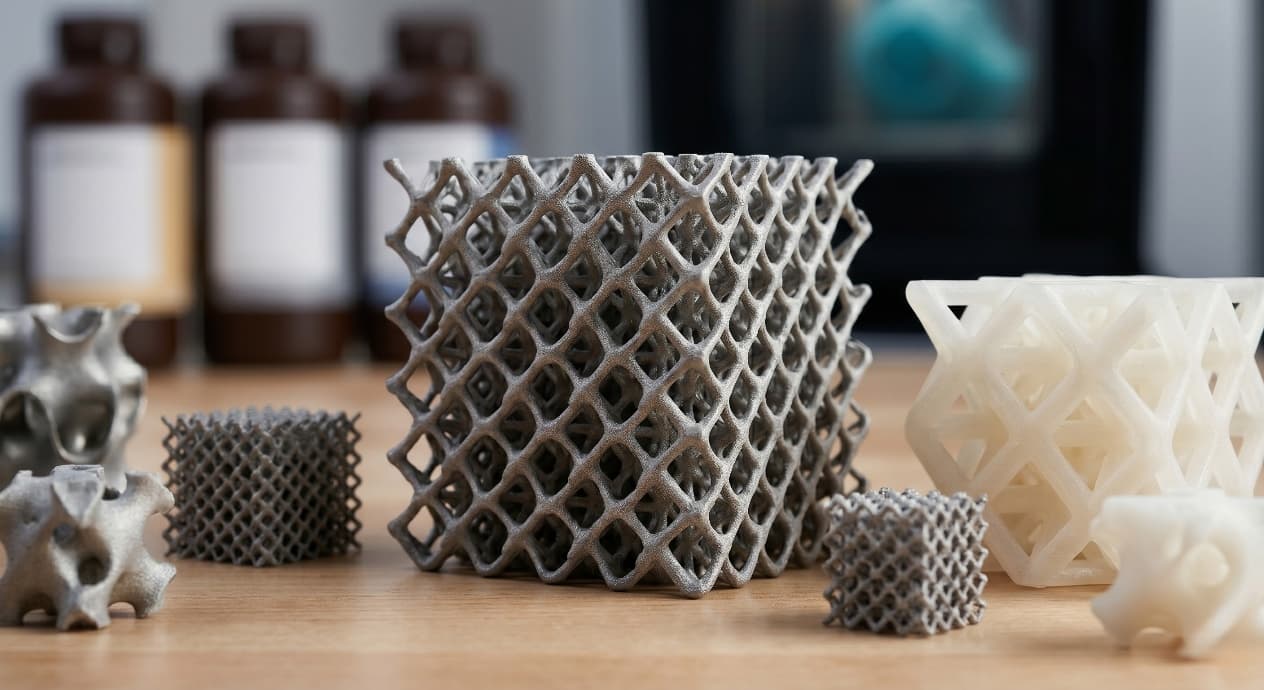
Every lattice solver ships with a gallery of cell types. The four that appear in 90% of production work are simple cubic, BCC / FCC variants, gyroid, and Schwarz primitive — and they behave differently under load, during manufacturing, and during cleanup. Picking by picture is the most common mistake; picking by the load type and the process constraints is the discipline that makes lattice programmes work.
3D Printing: define requirements before selecting a process
Connect requirements, process decisions and inspection before the first build to reduce late design changes.
- 1Requirements
Function, service environment, quantity and failure risk
- 2Material and process
Material grade, build strategy, geometry and finishing
- 3Inspection
Critical dimensions, functional tests and lot records
Key design rules
Manufacturing Floors You Cannot Ignore
Lattice geometry that looks perfect in CAD can still fail at the printer. Each process has minimum strut diameters, minimum pore sizes, and support implications that place a hard floor below the designer's intent. A BCC lattice with 0.
| Process | Minimum strut diameter | Minimum pore / cell size (for cleanup) | Main constraint |
|---|---|---|---|
| SLS / MJF (polymer) | 0.8 mm | 3 mm cell, 1.5 mm pore openings | Powder must have escape path to every internal region |
| DMLS / SLM (metal) | 0.5 mm | 2 mm cell with support-free orientation | Thermal stress on fine struts; powder removal same issue |
| SLA / DLP resin | 0.4 mm | 2 mm cell with drainage | Uncured resin must drain before post-cure |
| FDM (filament) | 1.0–1.5 mm | 4 mm cell | Extrusion path width limits finest feature |
| Carbon DLS | 0.5 mm | 3 mm cell | Resin drainage + thermal cure step |
| PolyJet | 0.3 mm | 2 mm cell with support-gel washout | Support gel must be rinsed from every channel |
The Skin-to-Lattice Interface Is Where It Breaks
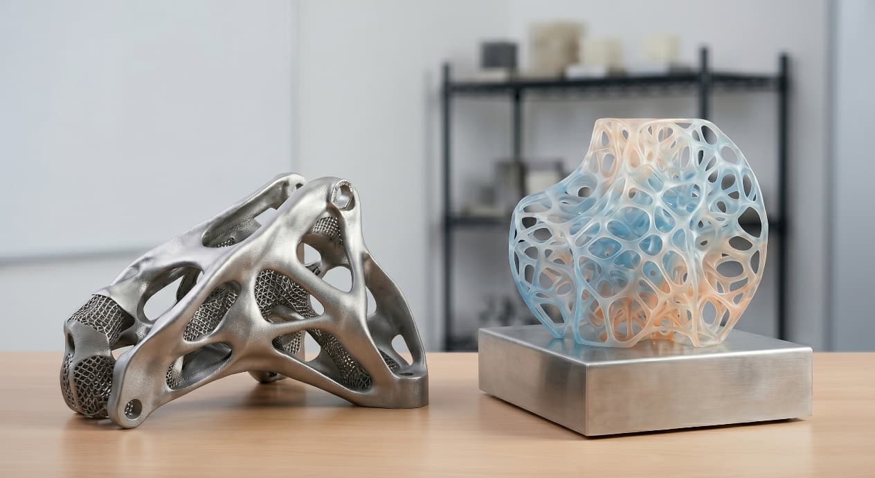
Most lattice failures do not happen in the cells. They happen at the boundary where the solid skin meets the open lattice. An abrupt transition concentrates stress at the interface; the skin peels or the outer struts shear.
From prototyping and finishing to acceptance
3D Printing: four checks before RFQ
- Function
State what the part must do and where it will be used
- Material and process
Name the required grade or performance range
- Design controls
Mark critical geometry, orientation and finishing
- Acceptance
Define dimensions, tests and required records
Pre-RFQ review: recommended practice and common mistakes
| Recommended practice | Common mistake |
|---|---|
| Start from the engineering objective (mass / impact / flow / stiffness) | Start from a cool-looking cell pattern |
| Grade density by load — denser near bosses and interfaces | Rub one cell pattern over the whole interior |
| Match cell type to load type (gyroid for bending, BCC for compression) | Assume one cell works for every load |
| Check the minimum strut / pore against the chosen process before drawing | Draw 0.5 mm struts and hope SLS will resolve them |
| Blend the skin into the lattice over ≥ 2 cell widths | End the skin abruptly at the lattice boundary |
| Add powder / resin escape paths to every enclosed region | Ship a sealed lattice volume |
- Engineering objective is named (mass / impact / flow / stiffness / acoustic) and a target number is written.
- Cell type matches the dominant load the region carries, not the cell picture that looks best.
- Density is graded by load path — denser at bosses / interfaces / load corridors, sparser in dead zones.
- Minimum strut and minimum pore both sit above the chosen process's floor, with margin.
- Skin-to-lattice transition is blended over at least two cell widths.
FAQ, further reading and sources
What should you define first for 3D Printing?
Define the operating environment, functional load, quantity and acceptance criteria before choosing a process. Those requirements determine the material, design rules and inspection plan.
Can the typical values in this guide be released directly on a drawing?
No. Use them for early design, then confirm the exact grade, supplier capability, DFM response and first-article result.
What should be locked before scaling production?
Lock the material, process settings, orientation, finishing and inspection method. Confirm that different lots reproduce the first-article result before scaling.
Next, explore 3D printing services, materials, online quoting, and the related design guides linked below.