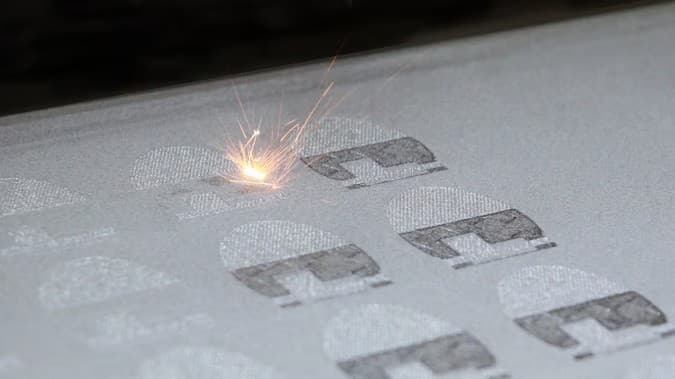
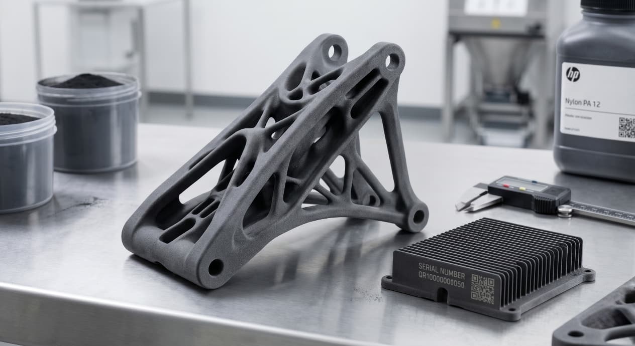
Redefining Metal Part Design With 3D Printing

Content in this Article
3D Printing can look straightforward in CAD and still fail after printing, finishing or inspection. The useful question is not whether a process can make the geometry once, but whether the chosen material, orientation and acceptance method can deliver the required function repeatedly. This guide turns that decision into a practical review workflow.
- Define the operating environment, functional load, quantity and acceptance criteria before choosing a process.
- Treat dimensions and performance values as design-starting points; confirm the exact grade and supplier capability before release.
- Use a first article or pilot lot to lock inspection and process controls before scaling.

Start with requirements and process selection
Why Redesign, Not Re-Print
Printing a CNC-shaped part on a laser powder-bed machine almost always loses on cost, lead time, and quality. The geometry assumes tool access, draft angles, and split lines that the printer does not need — and cannot exploit. The redesign mindset asks: if every constraint of milling, casting, and forging disappeared overnight, what would this part actually look like?
Three levers do most of the work: removing material that no longer carries load (topology), merging assemblies that no longer need joints (consolidation), and embedding function inside the wall (channels, lattices, sensors). The rest of this guide walks through each lever and the design moves that make them pay back.
Subtractive vs. Additive: What's Removed, What's Added
The constraint set is not smaller — it is different. Designers who only celebrate the removed limits get burned by the new ones (overhang angles, support contact, residual stress, powder evacuation).
| Constraint | Subtractive | Metal Additive |
|---|---|---|
| Tool access | Required for every feature | Not required |
| Draft / split lines | Mandatory | None |
| Internal cavities | Hard or impossible | Native |
| Overhang angle | N/A | ≥ 45° unsupported (typical) |
| Residual stress | Minor | Dominant — must be designed for |
| Powder evacuation | N/A | Drain holes ≥ 4 mm required |
3D Printing: define requirements before selecting a process
Connect requirements, process decisions and inspection before the first build to reduce late design changes.
- 1Requirements
Function, service environment, quantity and failure risk
- 2Material and process
Material grade, build strategy, geometry and finishing
- 3Inspection
Critical dimensions, functional tests and lot records
Key design rules
Topology Optimisation: When the Math Pays Back
Topology optimisation is not a styling tool. It is a load-case solver that needs honest boundary conditions, an honest mass target, and an honest manufacturing filter. Skip any of those three and you get an organic-looking part that fails qualification.
| Step | Input | Designer's job |
|---|---|---|
| 1. Design space | CAD envelope | Mark keep-out and load-bearing volumes |
| 2. Load cases | FEA + service data | Cover fatigue, not just yield |
| 3. Mass target | % of original | Set 30–60% — not 90% |
| 4. Mfg filter | Min member, overhang | Match the printer, not a generic preset |
| 5. Reconstruction | Solver mesh | Rebuild as parametric CAD for tolerancing |
| 6. Verification | FEA + print | Re-run FEA on the rebuilt model, not the raw mesh |
Payback is non-linear: the first 30% mass cut is usually free, the next 20% costs design hours, and anything beyond 60% removal typically demands a material change or load-case renegotiation with the systems team.
Internal Channels: Designing Function Into the Wall
Once you accept that the inside of the wall is design space, the part stops being a shell and becomes a system. Cooling, lubrication, instrumentation wiring, and pressure equalisation can all run inside a single body — provided the channels respect minimum diameter, drain orientation, and the ≥ 45° self-supporting rule.
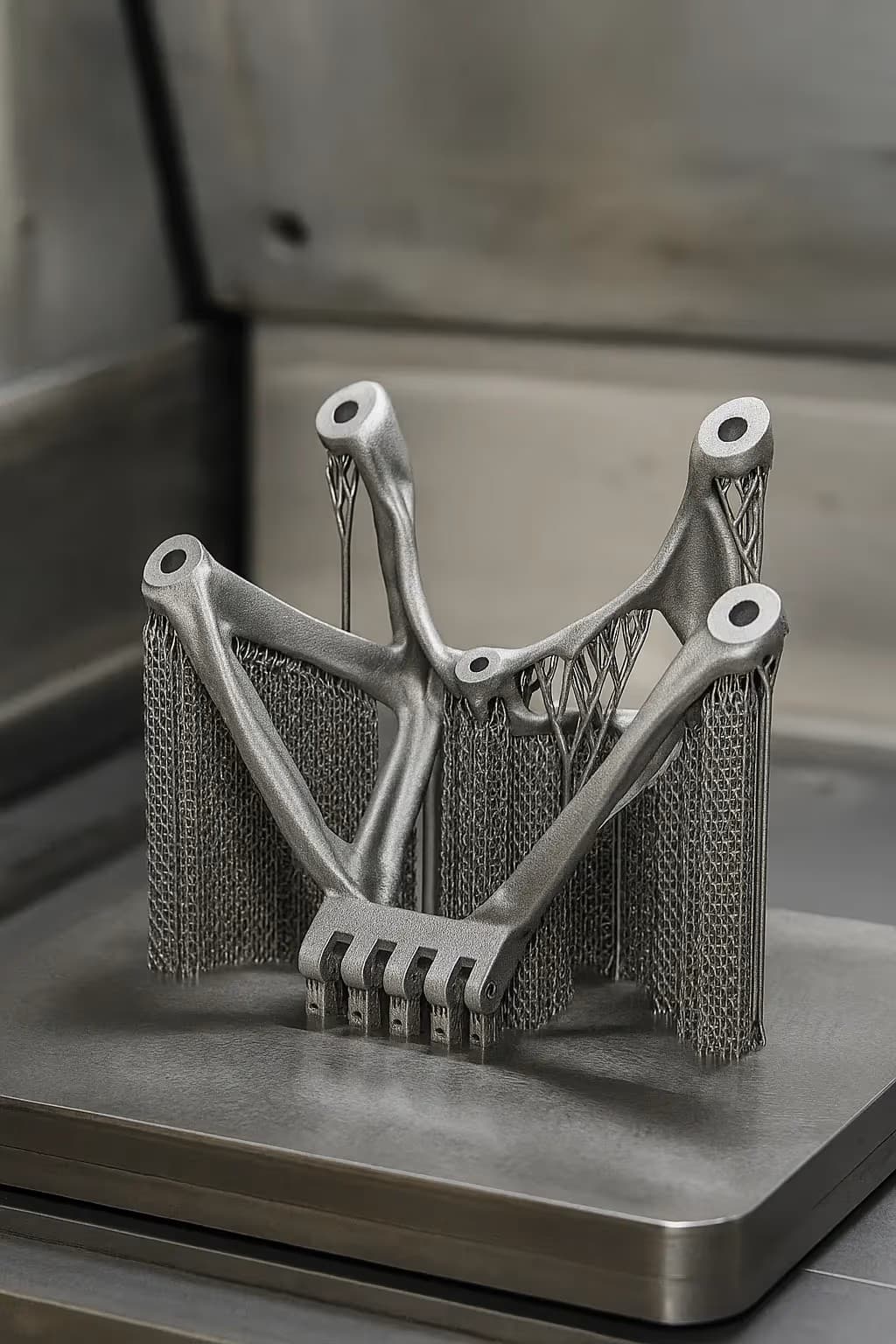
From prototyping and finishing to acceptance
3D Printing: four checks before RFQ
- Function
State what the part must do and where it will be used
- Material and process
Name the required grade or performance range
- Design controls
Mark critical geometry, orientation and finishing
- Acceptance
Define dimensions, tests and required records
Pre-RFQ review: recommended practice and common mistakes
| Recommended practice | Common mistake |
|---|---|
| Start from load paths and fluid paths, not from the legacy CAD model | Print a part that was designed for milling — redesign it or keep milling it |
| Set a mass target between 30–60% before opening the topology solver | Chase 80%+ mass removal without a material or load-case change |
| Add ≥ 4 mm drain holes in every internal cavity, oriented for gravity-assisted evacuation | Place precision bores or sealing faces directly on as-printed surfaces |
| Re-run FEA on the parametrically rebuilt geometry, not on the raw optimisation mesh | Ignore build orientation during concept design — it is a load-bearing decision |
- Load cases include fatigue, not only static yield.
- Mass target documented (30–60%) and signed off by systems engineer.
- Build orientation chosen; longest dimension aligned with build vector where possible.
- All overhangs verified ≥ 45° or supports planned and accessible.
- Drain holes ≥ 4 mm in every closed cavity, oriented for evacuation.
FAQ, further reading and sources
What should you define first for 3D Printing?
Define the operating environment, functional load, quantity and acceptance criteria before choosing a process. Those requirements determine the material, design rules and inspection plan.
Can the typical values in this guide be released directly on a drawing?
No. Use them for early design, then confirm the exact grade, supplier capability, DFM response and first-article result.
What should be locked before scaling production?
Lock the material, process settings, orientation, finishing and inspection method. Confirm that different lots reproduce the first-article result before scaling.
Next, explore 3D printing services, materials, online quoting, and the related design guides linked below.