DfAM for DMLS: Supports, Orientation, and Alloy-Aware Features
Content in this Article
3D Printing can look straightforward in CAD and still fail after printing, finishing or inspection. The useful question is not whether a process can make the geometry once, but whether the chosen material, orientation and acceptance method can deliver the required function repeatedly. This guide turns that decision into a practical review workflow.
- Define the operating environment, functional load, quantity and acceptance criteria before choosing a process.
- Treat dimensions and performance values as design-starting points; confirm the exact grade and supplier capability before release.
- Use a first article or pilot lot to lock inspection and process controls before scaling.

Start with requirements and process selection
Why DMLS Design Is Different
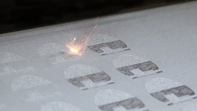
Direct Metal Laser Sintering melts metal powder layer by layer with a focused laser inside an inert chamber. Every layer cools at hundreds of degrees per second, locking residual stress into the part as it grows. Designing for DMLS means treating the build as a thermal-mechanical event, not just a geometry projection.
This guide focuses on the DfAM moves specific to powder-bed metal: alloy-aware minimum features, support design, build-plate attachment, recoater clearance, and nesting. For the mindset shift on part consolidation see the redefining-metal-part-design article; for heat treatment, HIP, and surface finishing see the post-processing guide.
Minimum Features by Alloy
Each alloy in the DMLS catalogue has its own laser absorption, melt-pool dynamics, and shrinkage behaviour. A 0. 4mm wall that prints cleanly in AlSi10Mg will warp in Inconel 718 and crack in copper.
| Alloy | Min wall (mm) | Min hole (mm) | Self-support angle | Max overhang w/o support |
|---|---|---|---|---|
| AlSi10Mg | 0.4 | 0.5 | 45 deg | 1.0mm |
| Ti6Al4V | 0.4 | 0.6 | 40 deg | 0.8mm |
| Inconel 718 | 0.5 | 0.7 | 45 deg | 0.6mm |
| 17-4PH SS | 0.5 | 0.6 | 45 deg | 1.0mm |
| CoCr | 0.5 | 0.7 | 40 deg | 0.6mm |
| Pure copper | 0.8 | 1.0 | 50 deg | 0.4mm |
3D Printing: define requirements before selecting a process
Connect requirements, process decisions and inspection before the first build to reduce late design changes.
- 1Requirements
Function, service environment, quantity and failure risk
- 2Material and process
Material grade, build strategy, geometry and finishing
- 3Inspection
Critical dimensions, functional tests and lot records
Key design rules
Orientation: Recoater, Stress, Down-facing
Orientation decides which surfaces become down-facing (rough), which faces resist load along the build direction (weakest in Z), and whether the recoater meets a long flat edge or a gentle curve. The wrong orientation can double support volume and triple post-machining time.
| Concern | Rule of thumb | Failure mode if violated |
|---|---|---|
| Recoater clash | Tilt long edges 5-15 deg off recoater axis | Edge curl, blade strike, build crash |
| Stress axis | Align primary load 0-30 deg from Z | Layer-line fatigue cracks |
| Down-facing limit | Keep critical surfaces above 45 deg | Dross, Ra > 20um, support scarring |
| Thermal mass | Stagger thick sections in Z | Warpage, plate detachment |
| Powder removal | Slope all internal channels >5 deg | Trapped sintered powder |
Machining Stock by Feature
DMLS reaches Ra 6-12um as-built; bearing fits, sealing faces, and threaded holes need machining. Add stock as offset bodies in CAD so the printed shape, the post-HIP shape, and the machined shape are three distinct files in your PLM.
| Feature | Stock per side (mm) | Why |
|---|---|---|
| Bearing bore H7 | 0.5 | Round-up after HIP shrinkage |
| Sealing face | 0.3 | Ra 0.8 finish target |
| Threaded hole | Drill+tap from solid | Avoid printed thread fatigue |
| Datum surface | 0.4 | Establish before HIP |
| Mating flange | 0.5 | Flatness < 0.05mm |
| Cosmetic only | 0.2 or none | Bead blast acceptable |

From prototyping and finishing to acceptance
3D Printing: four checks before RFQ
- Function
State what the part must do and where it will be used
- Material and process
Name the required grade or performance range
- Design controls
Mark critical geometry, orientation and finishing
- Acceptance
Define dimensions, tests and required records
Pre-RFQ review: recommended practice and common mistakes
| Recommended practice | Common mistake |
|---|---|
| Lock alloy before final CAD | Treat alloy as a late swap |
| Tilt long edges off recoater axis | Place flat tops parallel to blade |
| Add two openings per cavity | Rely on a single drain hole |
| Plan support removal access | Use lattice where no tool reaches |
| Add stock to bearing and seal faces | Trust as-built Ra on critical fits |
| Stagger thick sections in Z | Stack thermal mass in one slice |
- Alloy locked and tagged on every wall, hole, overhang
- All overhangs at least 5 deg above alloy self-support angle
- Long edges tilted 5-15 deg off recoater axis
- Two openings on every internal cavity, both labelled
- Support type chosen per zone with removal path verified
FAQ, further reading and sources
What should you define first for 3D Printing?
Define the operating environment, functional load, quantity and acceptance criteria before choosing a process. Those requirements determine the material, design rules and inspection plan.
Can the typical values in this guide be released directly on a drawing?
No. Use them for early design, then confirm the exact grade, supplier capability, DFM response and first-article result.
What should be locked before scaling production?
Lock the material, process settings, orientation, finishing and inspection method. Confirm that different lots reproduce the first-article result before scaling.
Next, explore 3D printing services, materials, online quoting, and the related design guides linked below.