Designing for Selective Laser Sintering — The DfSLS Playbook
Content in this Article
3D Printing can look straightforward in CAD and still fail after printing, finishing or inspection. The useful question is not whether a process can make the geometry once, but whether the chosen material, orientation and acceptance method can deliver the required function repeatedly. This guide turns that decision into a practical review workflow.
- Define the operating environment, functional load, quantity and acceptance criteria before choosing a process.
- Treat dimensions and performance values as design-starting points; confirm the exact grade and supplier capability before release.
- Use a first article or pilot lot to lock inspection and process controls before scaling.

Start with requirements and process selection
Why DfSLS Is Its Own Discipline
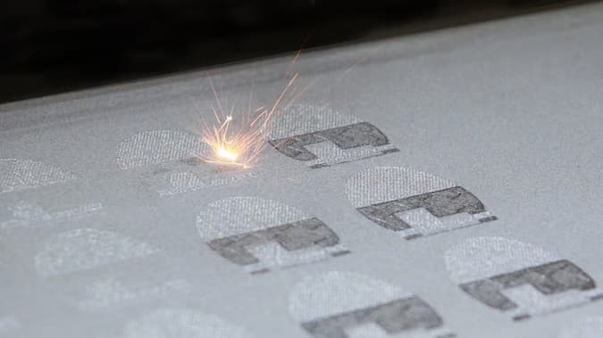
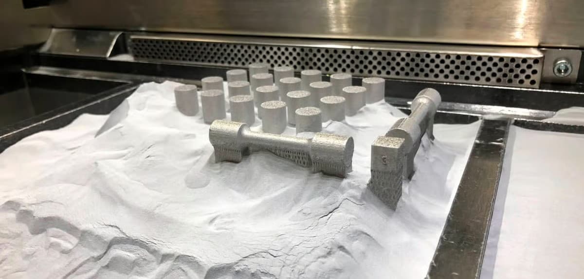
Most DfAM guides start from the assumption that the process needs supports, that downskin surfaces suffer, and that orientation is primarily a support-minimisation exercise. SLS inverts all three premises. Powder supports everything, every surface is an upskin of sorts, and orientation becomes a question of accuracy and thermal exposure rather than support cost.
If you already know which SLS polymer is right for the job — PA12, PA11, glass-filled, PP, or TPU — see the sibling article on SLS material families. This one assumes the material decision is made and focuses purely on geometry, orientation, consolidation, and the detail envelope you can realistically commit to on a drawing.
SLS DFM Reference Numbers
The table below is the single-sheet version our team pins above the design review screen. Numbers assume well-tuned industrial systems running PA12 in the 0. 10–0.
| Feature | Minimum | Reliable | Note |
|---|---|---|---|
| Unsupported wall | 0.7 mm | 1.0 mm | Below 0.7 mm parts warp or tear during depowder |
| Supported wall / rib | 0.4 mm | 0.6 mm | Must tie into bulk on both ends |
| Embossed text / lines | 0.5 mm wide × 0.5 mm tall | 0.8 × 0.8 mm | Debossed reads better than embossed |
| Through hole diameter | 1.5 mm | 2.0 mm | Holes print ~0.1–0.2 mm undersize |
| Escape hole for enclosed volume | 4.0 mm | 5.0 mm | One per cavity, diagonally placed if possible |
| Clearance between moving parts | 0.4 mm | 0.5 mm | Print-in-place hinges, links, joints |
3D Printing: define requirements before selecting a process
Connect requirements, process decisions and inspection before the first build to reduce late design changes.
- 1Requirements
Function, service environment, quantity and failure risk
- 2Material and process
Material grade, build strategy, geometry and finishing
- 3Inspection
Critical dimensions, functional tests and lot records
Key design rules
Consolidating Assemblies Into One Print
SLS shines when a bolted or bonded sub-assembly can be redrawn as a single part. The economics tip when piece-count savings outweigh the per-volume cost of nylon. Below is the rule-of-thumb matrix we use before committing to a redesign.
| Scenario | Consolidate? | Condition |
|---|---|---|
| ≤ 50 parts/yr, 5+ pieces | Yes | Piece-count and assembly labour dominate |
| 500 parts/yr, 3 pieces | Maybe | Check nylon volume vs injection tool amortisation |
| Moving mechanism, 3+ joints | Yes | Print-in-place eliminates fitters entirely |
| High-cycle load path | No | Layer-direction fatigue may fall below bolted |
| Needs metal thread insert | Partial | Consolidate body, keep heat-set inserts |
| Fluid manifold, internal routing | Yes | SLS removes cross-drilling and plugs |
Print-in-Place Mechanisms — Powder Is the Support
The design rule for print-in-place joints is simple: keep at least 0. 4 mm clearance on every sliding or rotating face, and make sure the powder in that gap has a path out. A 0.
Capture features — stops, retaining lips, pin heads — must still allow powder to escape during unpack. A common mistake is designing a retaining head with no powder relief: the joint prints but cannot be cleaned, and the mechanism freezes on arrival. Add a small side slot or route the relief through an adjacent face.

From prototyping and finishing to acceptance
Design Takeaways
DfSLS is the discipline of trading support-free freedom for a new set of constraints: escape holes, thermal bed position, print-in-place clearances, and orientation-driven accuracy. Teams that internalise those four constraints stop treating SLS as 'FDM with a nicer finish' and start using it for what it actually is — the shortest route from CAD to a moving, functional nylon part.
Pair this design thinking with the right polymer choice and you close the loop. The sibling SLS materials article covers the PA12 / PA11 / PA12-GF / PP / TPU decision; this article covers the geometry you hang on that material. Together they are the complete front end of an SLS production plan.
3D Printing: four checks before RFQ
- Function
State what the part must do and where it will be used
- Material and process
Name the required grade or performance range
- Design controls
Mark critical geometry, orientation and finishing
- Acceptance
Define dimensions, tests and required records
Pre-RFQ review: recommended practice and common mistakes
| Recommended practice | Common mistake |
|---|---|
| Add a ≥ 4 mm escape hole to every enclosed volume | Leave decorative enclosed cavities sealed |
| Reserve centre-bed zone for tolerance-critical parts | Let the bureau nest critical parts at the bed edge |
| Use 0.4–0.5 mm gaps on print-in-place joints | Copy FDM clearances (0.2 mm) into SLS |
| Deboss text rather than emboss | Use 0.3 mm raised text and expect it to survive blasting |
| Keep layer axis away from round-hole axis | Print Ø2 mm holes with axis along Z |
| Design ribs into wide flats over 80 mm | Leave a 150 × 2 mm flat and expect it to stay flat |
- Every enclosed volume has at least one ≥ 4 mm escape hole.
- Print-in-place gaps are set to 0.4–0.5 mm, not FDM-style 0.2 mm.
- Tolerance-critical features are annotated for centre-bed, mid-height placement.
- Round holes on tight-fit features have their axis in-plane, not along Z.
- Text is debossed at ≥ 0.5 mm width and ≥ 0.5 mm depth.
FAQ, further reading and sources
What should you define first for 3D Printing?
Define the operating environment, functional load, quantity and acceptance criteria before choosing a process. Those requirements determine the material, design rules and inspection plan.
Can the typical values in this guide be released directly on a drawing?
No. Use them for early design, then confirm the exact grade, supplier capability, DFM response and first-article result.
What should be locked before scaling production?
Lock the material, process settings, orientation, finishing and inspection method. Confirm that different lots reproduce the first-article result before scaling.
Next, explore 3D printing services, materials, online quoting, and the related design guides linked below.