Prototyping with PolyJet 3D Printing

Content in this Article
3D Printing can look straightforward in CAD and still fail after printing, finishing or inspection. The useful question is not whether a process can make the geometry once, but whether the chosen material, orientation and acceptance method can deliver the required function repeatedly. This guide turns that decision into a practical review workflow.
- Define the operating environment, functional load, quantity and acceptance criteria before choosing a process.
- Treat dimensions and performance values as design-starting points; confirm the exact grade and supplier capability before release.
- Use a first article or pilot lot to lock inspection and process controls before scaling.

Start with requirements and process selection
How PolyJet differs from SLA and DLP
PolyJet jets tiny droplets of photopolymer from an inkjet-style print head and cures them with a UV lamp that follows the carriage. SLA and DLP instead pull a part out of a resin vat, curing one layer against a film or window.
| Attribute | PolyJet (jetting) | SLA / DLP (vat) |
|---|---|---|
| Build mechanism | UV-cured jetted droplets | Laser or projector cures liquid vat |
| Materials per build | Up to 7 in one print | One resin per print |
| Color | Full CMYKWCl voxel color | Single resin color |
| Layer thickness | 16–27 µm (high-res mode) | 25–100 µm typical |
PolyJet material palette for prototyping
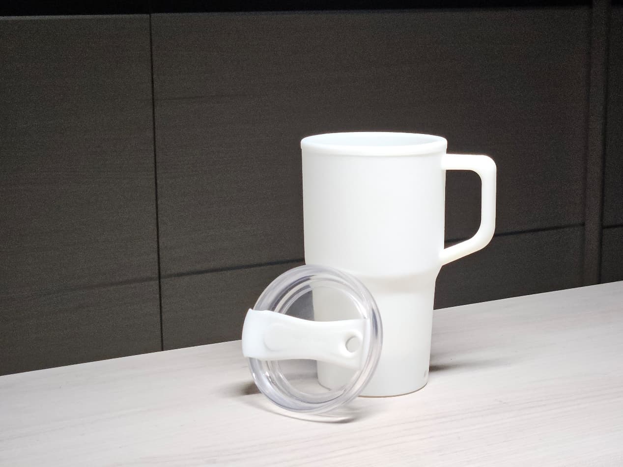
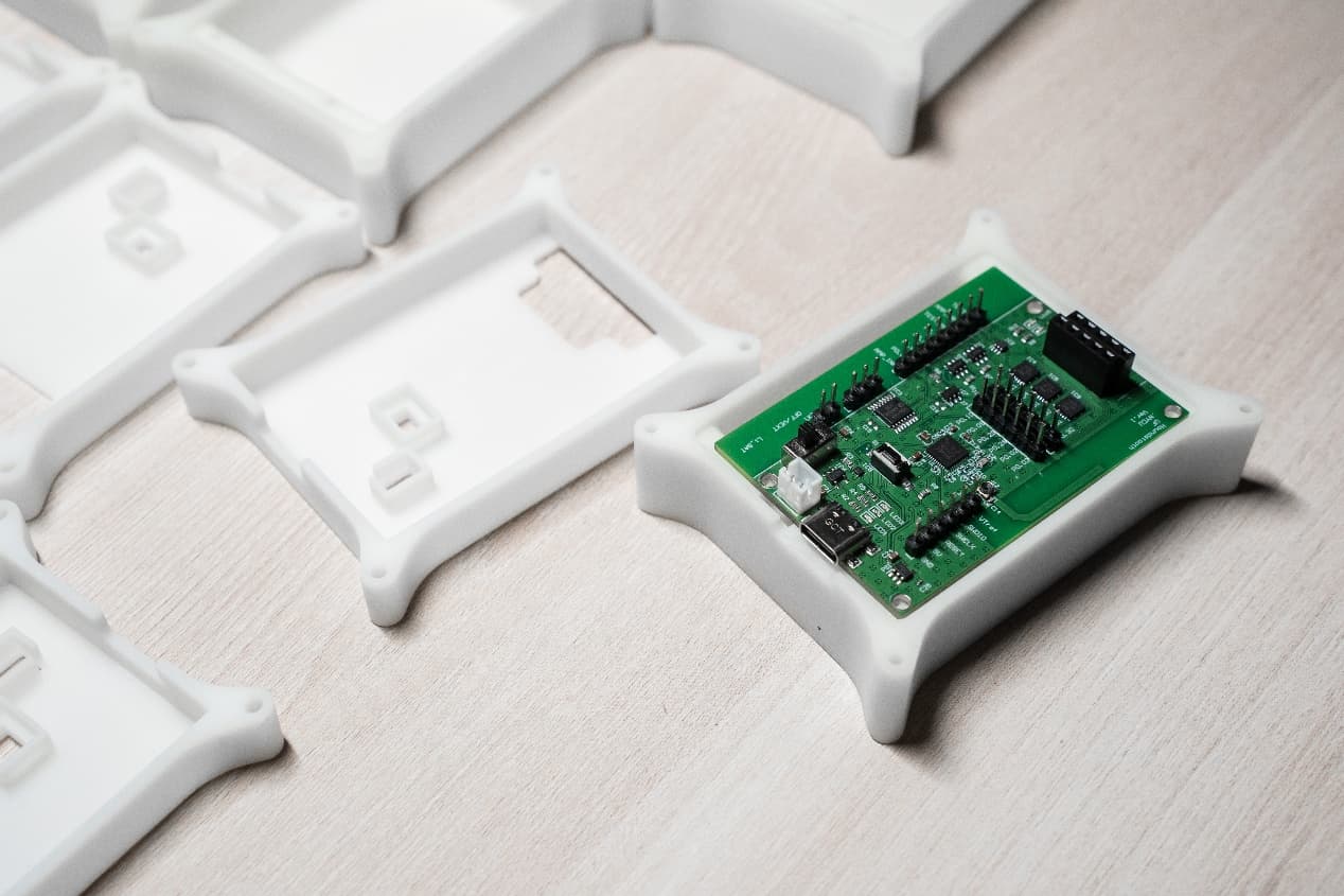
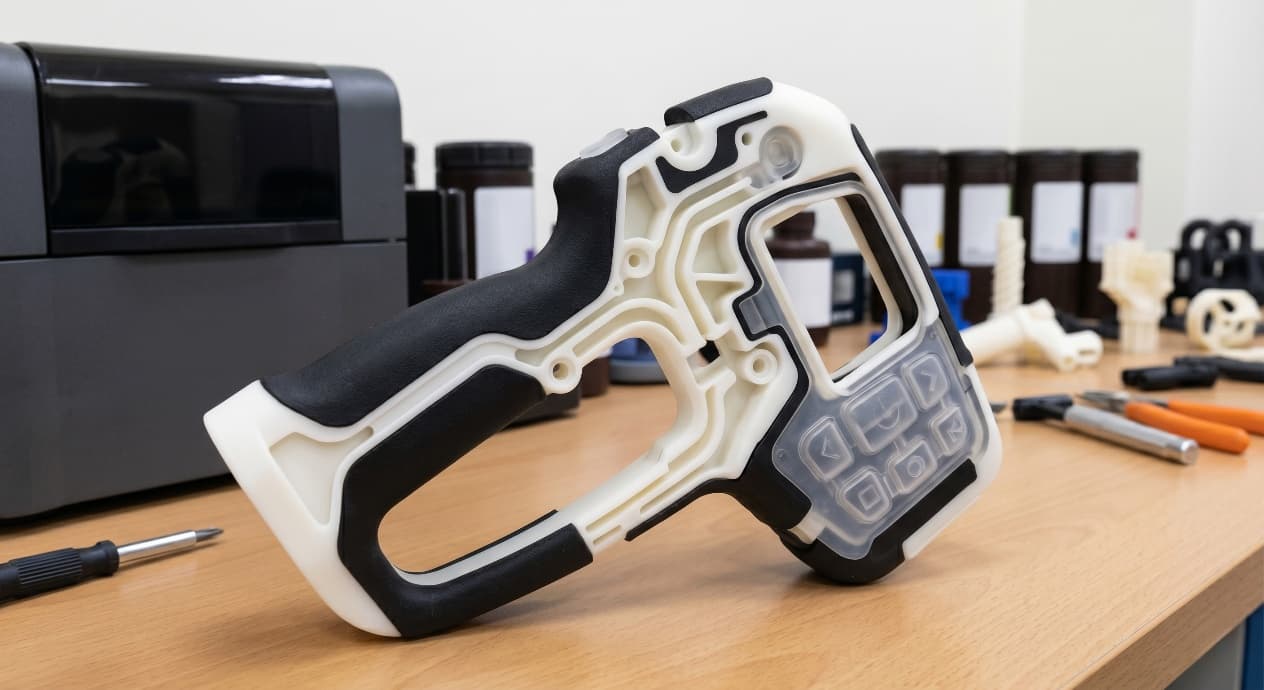
Stratasys groups PolyJet resins into families — Vero rigid opaque, VeroClear transparent, Agilus rubber-like, RGD high-temp, and DigitalABS simulated engineering plastic. For appearance and presentation work the star performers are VeroClear for lenses and fluid paths, VeroVivid CMYKW for Pantone color, and Vero rigid blends for chassis shells.
3D Printing: define requirements before selecting a process
Connect requirements, process decisions and inspection before the first build to reduce late design changes.
- 1Requirements
Function, service environment, quantity and failure risk
- 2Material and process
Material grade, build strategy, geometry and finishing
- 3Inspection
Critical dimensions, functional tests and lot records
Key design rules
DFM numbers to design against
PolyJet parts are forgiving geometrically but unforgiving mechanically. Design for the numbers below and the print will come off the tray looking the way the CAD promised; ignore them and walls will warp under support removal or fingernails.
| Feature | Minimum | Recommended |
|---|---|---|
| Layer thickness | 16 µm (high-res) | 27 µm (high-speed) |
| Wall thickness | 0.3 mm | 1.0 mm for handling |
| Embossed text height | 0.5 mm | 1.0 mm |
| Engraved text depth | 0.5 mm | 0.7 mm |
Appearance fidelity: voxel color and texture maps
On a J850 each voxel can be assigned a colour from a calibrated CMYKW + clear palette, which means your OBJ or 3MF texture map survives the print the way a 2D print survives an inkjet. Label artwork, IMD-style graphics, speaker grill patterns, and wood-grain finishes can all ship as part of the geometry.
From prototyping and finishing to acceptance
Anatomical, medical, and dental prototypes
Medical teams use PolyJet to translate DICOM segmentations directly into tactile replicas. Soft vasculature in Agilus30, calcified plaque in rigid Vero, and translucent organ tissue in VeroClear can coexist in one part.
3D Printing: four checks before RFQ
- Function
State what the part must do and where it will be used
- Material and process
Name the required grade or performance range
- Design controls
Mark critical geometry, orientation and finishing
- Acceptance
Define dimensions, tests and required records
Pre-RFQ review: recommended practice and common mistakes
| Recommended practice | Common mistake |
|---|---|
| Embed color in the 3MF/OBJ texture map | Paint PolyJet parts instead of using voxel color |
| Orient cosmetic faces skyward for lowest roughness | Hide cosmetic faces against the tray or support |
| Store finished parts out of direct UV | Leave PolyJet prototypes on a sunny desk for weeks |
| Use SUP707 soluble support for internal channels | Rely on manual support removal inside bores |
- Textures exported as 3MF or VRML with color per face or per voxel.
- Wall thicknesses at 1.0 mm or above on any surface a user will touch.
- Clear VeroClear parts oriented with the viewing face up and away from tray-contact.
- Support type set to SUP707 for any internal channel or narrow cavity.
- Glossy / matte finish selected deliberately per face — not left at printer default.
FAQ, further reading and sources
What should you define first for 3D Printing?
Define the operating environment, functional load, quantity and acceptance criteria before choosing a process. Those requirements determine the material, design rules and inspection plan.
Can the typical values in this guide be released directly on a drawing?
No. Use them for early design, then confirm the exact grade, supplier capability, DFM response and first-article result.
What should be locked before scaling production?
Lock the material, process settings, orientation, finishing and inspection method. Confirm that different lots reproduce the first-article result before scaling.
Next, explore 3D printing services, materials, online quoting, and the related design guides linked below.