Designing Parts for PolyJet Overmolding
Content in this Article
3D Printing can look straightforward in CAD and still fail after printing, finishing or inspection. The useful question is not whether a process can make the geometry once, but whether the chosen material, orientation and acceptance method can deliver the required function repeatedly. This guide turns that decision into a practical review workflow.
- Define the operating environment, functional load, quantity and acceptance criteria before choosing a process.
- Treat dimensions and performance values as design-starting points; confirm the exact grade and supplier capability before release.
- Use a first article or pilot lot to lock inspection and process controls before scaling.
Start with requirements and process selection
Why PolyJet Specifically — and Not SLA or SLS
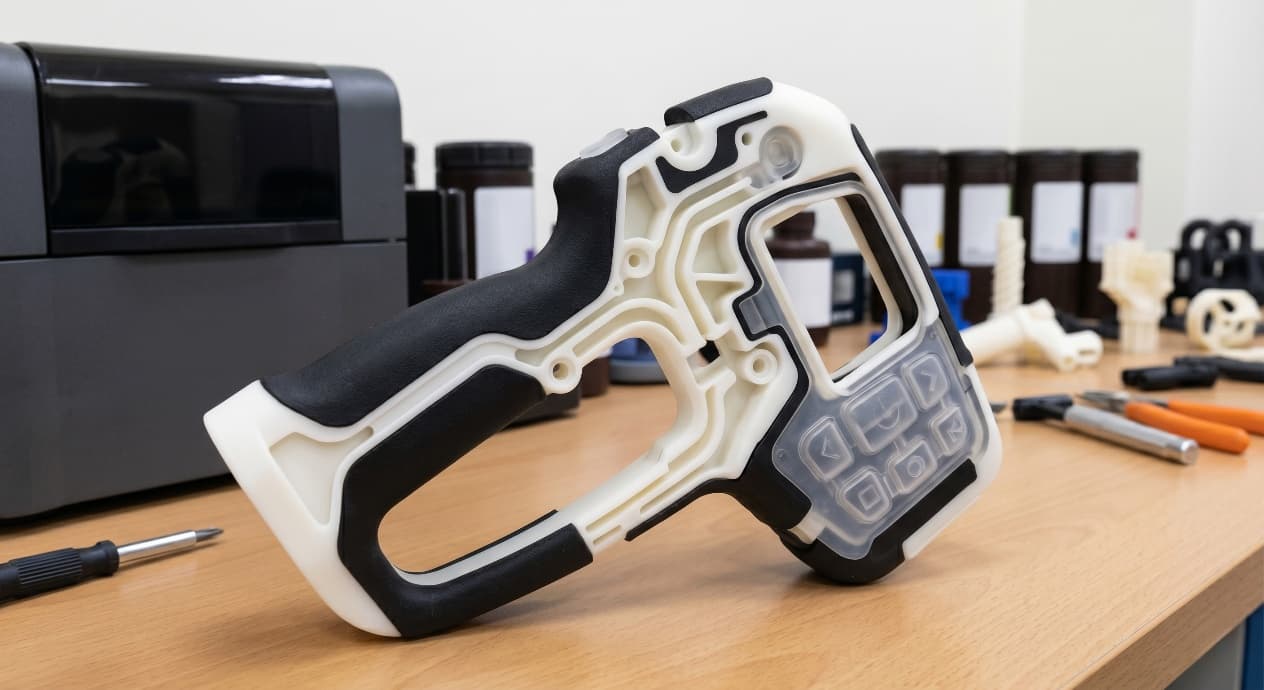
Multimaterial printing is not unique to PolyJet, but PolyJet is the only mainstream additive process that can place hard and soft regions side-by-side inside the same build without bonding, gluing, or a second operation. SLA can print flexible resins, but a rigid zone and a soft zone have to be printed as separate parts and joined.
The PolyJet Material Palette for Overmould Prototypes
Stratasys's PolyJet ecosystem splits into rigid families (Vero), digital elastomer families (Agilus and the older Tango), and clear options that can be mixed into either half. The "digital material" concept is what makes the palette feel much larger than the bottle count suggests: the machine can intermix two base resins at the voxel level to produce intermediate Shore values on demand, which is how a single build can hold 40A, 60A, and 80A zones simultaneously without loading three separate elastomer bottles.
| Material family | Role | Shore / property range | Typical use |
|---|---|---|---|
| VeroWhite / VeroBlack / VeroClear | Rigid substrate | ~83–85D, tensile 50–65 MPa | Housing, structural core |
| VeroClear (transparent rigid) | Optical rigid | ~83D, light transmission ~80% | Light pipes, transparent enclosures |
| Agilus30 (30 Shore A) | Soft elastomer | 30A, elongation ~220% | Soft-touch grips, cushioning zones |
| Agilus + Vero digital blend | Intermediate hardness | 35A–90A on demand | Tuneable grip, buttons, seals |
| Tango / TangoPlus (legacy) | Soft elastomer (older platforms) | 26–60 Shore A | Legacy compatibility, softer hand-feel |
3D Printing: define requirements before selecting a process
Connect requirements, process decisions and inspection before the first build to reduce late design changes.
- 1Requirements
Function, service environment, quantity and failure risk
- 2Material and process
Material grade, build strategy, geometry and finishing
- 3Inspection
Critical dimensions, functional tests and lot records
Key design rules
The CAD Setup That Prints What You Meant
Multimaterial success starts in the file, not at the machine. The single most common production failure — a soft zone that was supposed to be Shore 40A coming out either entirely rigid or with the wrong edge — traces back to ambiguous body definitions in CAD.
| CAD element | Requirement | Failure mode if skipped |
|---|---|---|
| Rigid substrate | Named solid body with explicit volume | Unassigned regions default to rigid — grip prints hard |
| Soft zone | Separate named body, non-zero thickness everywhere | Zero-thickness patches print as rigid or disappear |
| Transition interface | Coincident face between rigid and soft bodies | Gap → delamination; overlap → slicer ambiguity |
| Colour or hardness gradient | Assembly of multiple bodies, each a single target value | Smooth gradient breaks into visible banding |
| Clear accent / light-pipe | Separate VeroClear body with explicit boundary | Translucent region prints opaque or picks up adjacent material |
The Transition Edge Is the Design
The boundary between rigid and soft is the feature users touch, look at, and judge. Four transition geometries show up repeatedly in production overmould designs, and PolyJet prototyping should test the one that matches the final intent, not the one that is easiest to model.
From prototyping and finishing to acceptance
3D Printing: four checks before RFQ
- Function
State what the part must do and where it will be used
- Material and process
Name the required grade or performance range
- Design controls
Mark critical geometry, orientation and finishing
- Acceptance
Define dimensions, tests and required records
Pre-RFQ review: recommended practice and common mistakes
| Recommended practice | Common mistake |
|---|---|
| Use PolyJet to decide durometer, placement, and transition geometry | Use PolyJet to validate long-term bond strength |
| Model every zone as a separately named solid body | Express soft zones as paint breaks or notes |
| Specify the transition type explicitly (sharp / filleted / pad / lip) | Leave the transition to slicer or shop-floor interpretation |
| Print a direct A/B comparison when a decision is contested | Print one build and assume review will choose |
| Print at real user-contact scale and review in the hand | Review multimaterial designs only on screen |
- The question this prototype answers is named explicitly (durometer, placement, transition geometry, visual split).
- Every rigid zone, soft zone, and accent (clear / high-temp) is modelled as a separately named solid body.
- No zero-thickness patches anywhere the soft material appears.
- Minimum soft wall is 0.6 mm; minimum transition fillet is 0.5 mm.
- Any encapsulated soft cavity has an escape path of at least 1.0 mm.
FAQ, further reading and sources
What should you define first for 3D Printing?
Define the operating environment, functional load, quantity and acceptance criteria before choosing a process. Those requirements determine the material, design rules and inspection plan.
Can the typical values in this guide be released directly on a drawing?
No. Use them for early design, then confirm the exact grade, supplier capability, DFM response and first-article result.
What should be locked before scaling production?
Lock the material, process settings, orientation, finishing and inspection method. Confirm that different lots reproduce the first-article result before scaling.
Next, explore 3D printing services, materials, online quoting, and the related design guides linked below.