How to Design STL Files for 3D Printing in Your CAD Program
Content in this Article
3D Printing can look straightforward in CAD and still fail after printing, finishing or inspection. The useful question is not whether a process can make the geometry once, but whether the chosen material, orientation and acceptance method can deliver the required function repeatedly. This guide turns that decision into a practical review workflow.
- Define the operating environment, functional load, quantity and acceptance criteria before choosing a process.
- Treat dimensions and performance values as design-starting points; confirm the exact grade and supplier capability before release.
- Use a first article or pilot lot to lock inspection and process controls before scaling.
Start with requirements and process selection
STL vs Modern Alternatives
STL turned 37 years old in 2025. It stores only triangle vertices and normals, nothing about units, color, materials, lattices, or assemblies.
| Format | Geometry type | Carries | Best use | Limits |
|---|---|---|---|---|
| STL | Triangle mesh | Vertices, normals | Universal slicer input | No units, color, or metadata |
| 3MF | Triangle mesh + XML | Units, color, materials, supports, print settings | Modern FDM/SLA/MJF with compatible slicer | Requires modern toolchain |
| STEP | B-rep solid | Exact surfaces, assemblies, tolerances | Design handoff, reverse conversion | Slicers cannot read directly |
| OBJ | Polygon mesh | Vertices, normals, textures, materials | Full-color visualization, MJF with color | Larger file, not native to most slicers |
Chord Tolerance, Triangle Count, and File Size
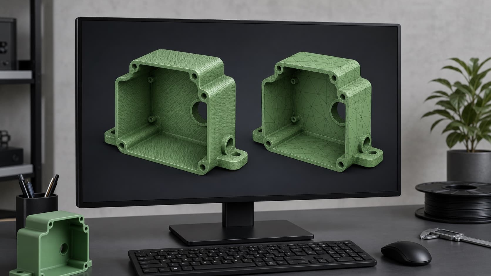
Chord tolerance (also called deviation, or chord height) is the maximum distance between the tessellated triangle and the true CAD surface. Halve the tolerance and triangle count roughly quadruples on curved surfaces.
3D Printing: define requirements before selecting a process
Connect requirements, process decisions and inspection before the first build to reduce late design changes.
- 1Requirements
Function, service environment, quantity and failure risk
- 2Material and process
Material grade, build strategy, geometry and finishing
- 3Inspection
Critical dimensions, functional tests and lot records
Key design rules
Common STL Errors and What They Break
Slicers read STL as a closed volume. Any defect that breaks 'closed' makes the slicer either guess (filling holes badly), refuse the file, or silently produce air-printed regions.
| Error | What it is | Downstream effect | Typical CAD cause |
|---|---|---|---|
| Non-manifold edge | Edge shared by > 2 faces | Slicer rejects or prints chaos | Zero-thickness surface, coincident bodies |
| Flipped normal | Triangle facing inward | Slicer inverts inside/outside | Mirrored feature, bad boolean |
| Hole in mesh | Missing triangle | Slicer fills with random plane | Tessellation failure at sharp fillet |
| Self-intersection | Triangles pass through each other | Double walls, wrong volume | Overlapping bodies not merged |
Units are the least glamorous and most catastrophic trap. STL carries no unit tag: the number '25.
From prototyping and finishing to acceptance
3D Printing: four checks before RFQ
- Function
State what the part must do and where it will be used
- Material and process
Name the required grade or performance range
- Design controls
Mark critical geometry, orientation and finishing
- Acceptance
Define dimensions, tests and required records
Pre-RFQ review: recommended practice and common mistakes
| Common mistake | Likely outcome | How to improve |
|---|---|---|
| Export binary STL | Use ASCII STL for production | Binary is 5–8x smaller and faster to read |
| Set document units to mm | Rely on slicer to guess | STL has no unit tag |
| Run watertight check before export | Trust visual inspection | Gaps under 0.05 mm are invisible on screen |
| Scale chord tol. to smallest feature | Apply one tolerance to all parts | Micro-features need micron-level mesh |
- Document units set to mm and verified on the title block
- All helper surfaces, sketches, and zero-thickness bodies deleted
- Watertight / non-manifold check passed inside CAD
- Chord tolerance scaled to smallest feature, angular at 5 deg or finer
- Mirrors and booleans inspected with normal-shading view
FAQ, further reading and sources
What should you define first for 3D Printing?
Define the operating environment, functional load, quantity and acceptance criteria before choosing a process. Those requirements determine the material, design rules and inspection plan.
Can the typical values in this guide be released directly on a drawing?
No. Use them for early design, then confirm the exact grade, supplier capability, DFM response and first-article result.
What should be locked before scaling production?
Lock the material, process settings, orientation, finishing and inspection method. Confirm that different lots reproduce the first-article result before scaling.
Next, explore 3D printing services, materials, online quoting, and the related design guides linked below.