How to Design for Nylon 3D Printing
Content in this Article
3D Printing can look straightforward in CAD and still fail after printing, finishing or inspection. The useful question is not whether a process can make the geometry once, but whether the chosen material, orientation and acceptance method can deliver the required function repeatedly. This guide turns that decision into a practical review workflow.
- Define the operating environment, functional load, quantity and acceptance criteria before choosing a process.
- Treat dimensions and performance values as design-starting points; confirm the exact grade and supplier capability before release.
- Use a first article or pilot lot to lock inspection and process controls before scaling.
Start with requirements and process selection
Nylon Families You Actually Choose Between
Five variants cover 95% of commercial nylon AM today: PA12 (the workhorse), PA11 (ductile and bio-based), PA12-GF (glass filled for stiffness), PA12-CF (carbon fiber for specific stiffness), and PA12 mineral-filled (dimensional stability for housings). Each has different tensile strength, modulus, heat deflection temperature (HDT), elongation at break, and price.
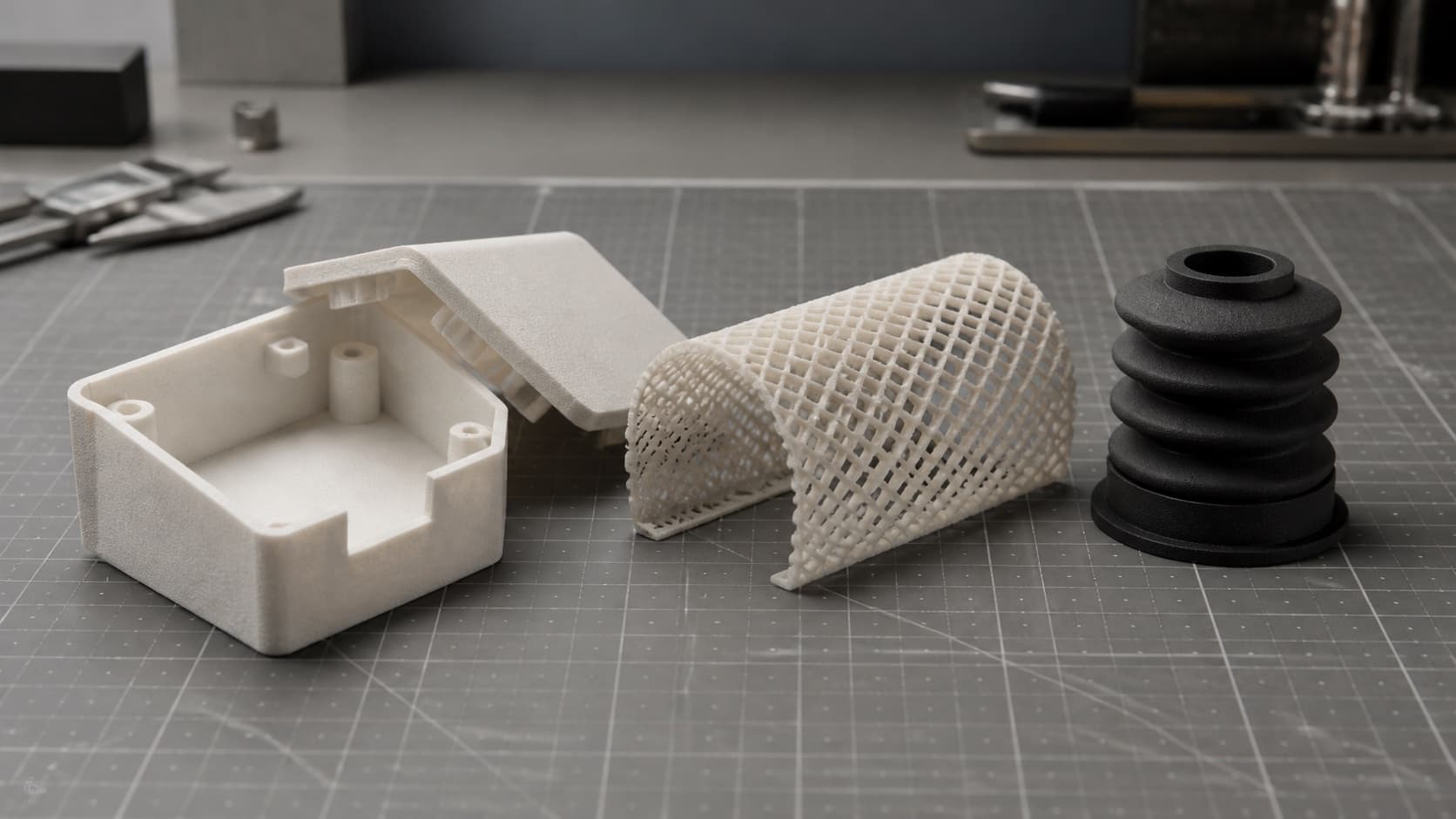
Read the table below as a trade space rather than a ranking. PA11 is not better than PA12; it is better when you need impact and fatigue.
| Variant | Tensile (MPa) | Modulus (GPa) | HDT @0.45 MPa (C) | Elongation (%) | Relative Cost |
|---|---|---|---|---|---|
| PA12 (SLS/MJF) | 48 | 1.7 | 170 | 20 | 1.0x |
| PA11 | 52 | 1.5 | 180 | 45 | 1.4x |
| PA12-GF (30%) | 52 | 3.2 | 175 | 9 | 1.3x |
| PA12-CF (10-15%) | 75 | 5.5 | 180 | 5 | 2.1x |
3D Printing: define requirements before selecting a process
Connect requirements, process decisions and inspection before the first build to reduce late design changes.
- 1Requirements
Function, service environment, quantity and failure risk
- 2Material and process
Material grade, build strategy, geometry and finishing
- 3Inspection
Critical dimensions, functional tests and lot records
Key design rules
Concrete DFM Numbers for Nylon Powder Bed
These are the working limits we use when quoting MJF and SLS PA12. Treat them as the design floor; go thicker for load paths and tolerance-sensitive features.
| Feature | PA12 | PA11 | PA12-GF | Note |
|---|---|---|---|---|
| Min wall | 1.0 mm | 1.0 mm | 1.2 mm | Unsupported wall 0.7 mm risky |
| Min hole diameter | 1.5 mm | 1.5 mm | 2.0 mm | Below this, powder trapping |
| Assembly clearance | 0.4 mm | 0.4 mm | 0.5 mm | Per mating face |
| Living hinge | 0.6 mm | 0.5 mm | N/A | PA11 doubles cycle life |
Moisture: The Hidden Variable in Every Nylon Part
Nylon is hygroscopic. A PA12 part shipped dry-as-printed at 0.
From prototyping and finishing to acceptance
Post-Processing: Finish Options for Nylon
Choose finishing for a reason: grip, appearance, sealing, or dimensional cleanup. Each step adds or removes thickness and changes surface chemistry, so DFM must anticipate it before you ship files.
| Finish | Thickness Delta | Ra After (um) | Typical Use | Cost Adder |
|---|---|---|---|---|
| Bead blast | -0.02 mm | 6-8 | Default matte | +5% |
| Vibratory tumble | -0.05 mm | 3-5 | Consumer feel | +10% |
| Vapor smoothing | +0.08 mm | 1-2 | Sealed / waterproof | +25% |
| Dye (black) | +0 mm | same | Cosmetics | +8% |
3D Printing: four checks before RFQ
- Function
State what the part must do and where it will be used
- Material and process
Name the required grade or performance range
- Design controls
Mark critical geometry, orientation and finishing
- Acceptance
Define dimensions, tests and required records
Pre-RFQ review: recommended practice and common mistakes
| Recommended practice | Common mistake |
|---|---|
| Use 1.0-1.2 mm minimum walls with ribs | Leave large flat surfaces unsupported |
| Add 4 mm escape holes on enclosed cavities | Trap powder in closed volumes |
| Fillet every internal corner (>=0.8 mm) | Leave sharp inside corners under load |
| Condition to end-use humidity before measurement | Tolerance on dry-as-printed dimensions |
- Variant chosen against load case (PA12 / PA11 / GF / CF / mineral) and documented.
- All walls >= 1.0 mm (1.2 mm for GF); ribs added where unsupported.
- Every internal corner filleted to >= 0.8 mm.
- At least one 4 mm escape hole per 100 cc of enclosed cavity.
- Assembly clearances set against conditioned (not dry) dimensions.
FAQ, further reading and sources
What should you define first for 3D Printing?
Define the operating environment, functional load, quantity and acceptance criteria before choosing a process. Those requirements determine the material, design rules and inspection plan.
Can the typical values in this guide be released directly on a drawing?
No. Use them for early design, then confirm the exact grade, supplier capability, DFM response and first-article result.
What should be locked before scaling production?
Lock the material, process settings, orientation, finishing and inspection method. Confirm that different lots reproduce the first-article result before scaling.
Next, explore 3D printing services, materials, online quoting, and the related design guides linked below.