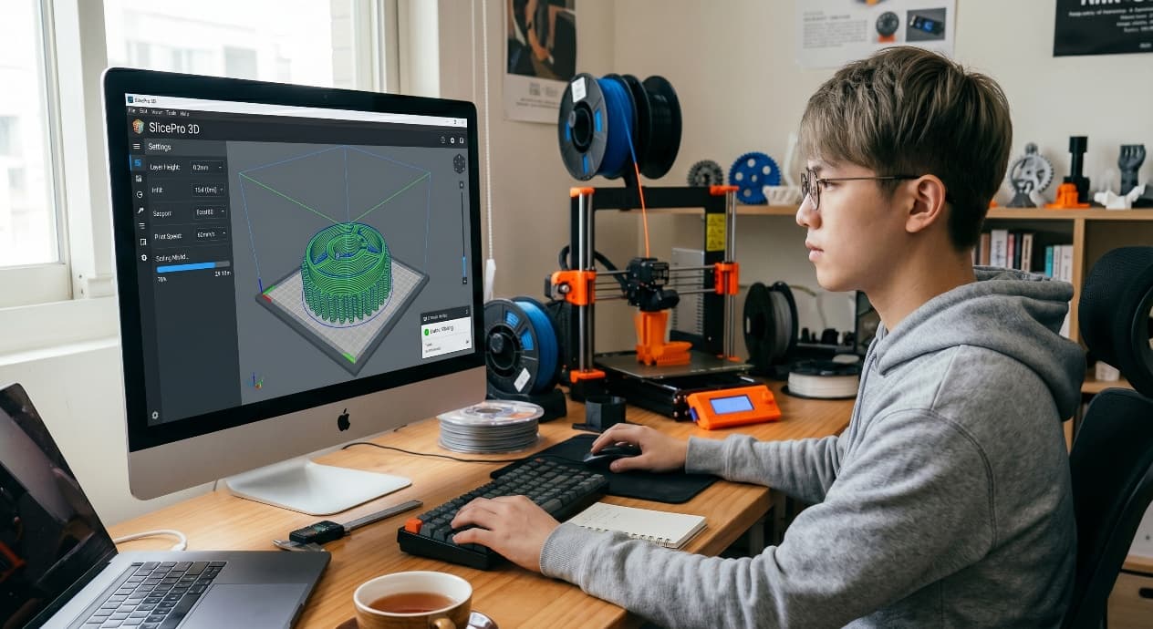
Designing Jigs and Fixtures for 3D Printing: DFM, Materials, and Shop-Floor Reality
Content in this Article
3D Printing can look straightforward in CAD and still fail after printing, finishing or inspection. The useful question is not whether a process can make the geometry once, but whether the chosen material, orientation and acceptance method can deliver the required function repeatedly. This guide turns that decision into a practical review workflow.
- Define the operating environment, functional load, quantity and acceptance criteria before choosing a process.
- Treat dimensions and performance values as design-starting points; confirm the exact grade and supplier capability before release.
- Use a first article or pilot lot to lock inspection and process controls before scaling.
Start with requirements and process selection
Jigs vs Fixtures vs Checking Gauges
These three words get used interchangeably on the shop floor, but they demand different tolerance budgets, different materials, and different service lives. Misclassifying a tool is the most common reason a printed aid disappoints in production — a fixture designed to a jig's tolerance will fail inspection, and a gauge built to a fixture's wear standard will drift out of calibration within weeks.
| Tool class | What it does | Typical tolerance | Typical service life |
|---|---|---|---|
| Jig | Guides a tool or process (drilling, routing, bonding) | ±0.10–0.20 mm | 3–12 months, 5k–50k cycles |
| Fixture | Holds or locates a part during work | ±0.20–0.50 mm | 6–24 months, 10k–100k cycles |
| Checking gauge | Verifies part dimensions pass/fail | ±0.05 mm or tighter | Until calibration drift, recert every 6–12 months |
| Soft jaw / nest | Protects part surface while clamping | ±0.30 mm | Consumable, replace as wear dictates |
Material Selection for Printed Jigs
SLS/MJF PA12 GF is the workhorse for roughly 70% of printed production tooling because it balances stiffness, dimensional stability after conditioning, and cost. But the material choice should follow the load case, not the shop's default.
3D Printing: define requirements before selecting a process
Connect requirements, process decisions and inspection before the first build to reduce late design changes.
- 1Requirements
Function, service environment, quantity and failure risk
- 2Material and process
Material grade, build strategy, geometry and finishing
- 3Inspection
Critical dimensions, functional tests and lot records
Key design rules
DFM Numbers for Shop-Floor Reality
These are the dimensions that separate a fixture that works on day one from one that gets binned after a shift. They account for gloves, fatigue, part variation, and the fact that operators will push a tool harder than any CAD load case predicts.
| Feature | Recommended size | Reason |
|---|---|---|
| Handle diameter (grip) | 28–35 mm | Comfortable with nitrile gloves |
| Finger recess depth | ≥12 mm | Full fingertip purchase |
| Clearance to part under test | 0.25–0.40 mm per side | Absorbs part tolerance + thermal |
| Clamp feature threaded boss | M5 steel insert + 3 mm wall | Printed thread strips after 500 cycles |
| Mounting boss to work surface | M6, 4 mm wall, 15 mm deep | Survives lateral side loads |
Why Additive Beats CNC Aluminum at Low Volume
Below about 50 units per SKU, CNC aluminum carries fixed costs that additive simply does not have: programming (2–6 h), fixturing the raw stock, first-article inspection, and minimum-run pricing from job shops. A printed PA12 GF equivalent skips all four.
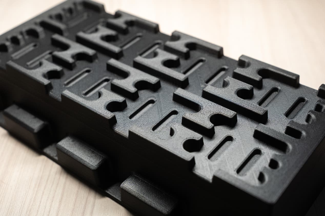
Geometry freedom is the second advantage. Printed fixtures can wrap around complex parts, integrate cable channels, hide sensor wiring, and carry conformal cooling or vacuum ports without any extra process step.
From prototyping and finishing to acceptance
Integrating Sensors, Inserts, and Standard Hardware
A printed fixture should treat printed plastic as structure and standard hardware as interface. Heat-set brass inserts (M3–M8) installed with a 280 °C soldering iron give threaded holes that outlast the fixture itself; press-fit steel dowel pins handle location to ±0.
For PCB assembly, integrated LEDs wired to a PoE switch and driven by the MES system can highlight the next placement location cycle by cycle. The fixture becomes a display surface, not just a holder — and because the geometry is printed, adding six new LEDs between revisions costs nothing beyond the LEDs themselves.
3D Printing: four checks before RFQ
- Function
State what the part must do and where it will be used
- Material and process
Name the required grade or performance range
- Design controls
Mark critical geometry, orientation and finishing
- Acceptance
Define dimensions, tests and required records
Pre-RFQ review: recommended practice and common mistakes
| Recommended practice | Common mistake |
|---|---|
| Use heat-set inserts for all threaded features | Tap threads directly into printed plastic for repeated use |
| Design locating features with lead-in chamfers (2 mm, 30°) | Rely on sharp-edged pockets to locate parts |
| Specify ESD-safe material for any electronics contact | Use standard PA12 near unpackaged boards |
| Add 0.25–0.40 mm clearance around the part under test | Copy CAD nominal dimensions directly into the nest |
| Print wear surfaces replaceable and bolted on | Treat the whole fixture as one sacrificial consumable |
- Tool class confirmed: jig, fixture, or gauge — tolerance budget matches.
- Material chosen against load case, not shop default; ESD spec flagged if near electronics.
- All threaded features use heat-set or press-fit metal inserts.
- Part-under-test clearance set to 0.25–0.40 mm per side.
- Wear surfaces isolated as replaceable sub-assemblies.
FAQ, further reading and sources
What should you define first for 3D Printing?
Define the operating environment, functional load, quantity and acceptance criteria before choosing a process. Those requirements determine the material, design rules and inspection plan.
Can the typical values in this guide be released directly on a drawing?
No. Use them for early design, then confirm the exact grade, supplier capability, DFM response and first-article result.
What should be locked before scaling production?
Lock the material, process settings, orientation, finishing and inspection method. Confirm that different lots reproduce the first-article result before scaling.
Next, explore 3D printing services, materials, online quoting, and the related design guides linked below.