Carbon DLS for Production Parts: A Design and Process Playbook
Content in this Article
3D Printing can look straightforward in CAD and still fail after printing, finishing or inspection. The useful question is not whether a process can make the geometry once, but whether the chosen material, orientation and acceptance method can deliver the required function repeatedly. This guide turns that decision into a practical review workflow.
- Define the operating environment, functional load, quantity and acceptance criteria before choosing a process.
- Treat dimensions and performance values as design-starting points; confirm the exact grade and supplier capability before release.
- Use a first article or pilot lot to lock inspection and process controls before scaling.

Start with requirements and process selection
What Carbon DLS Actually Is
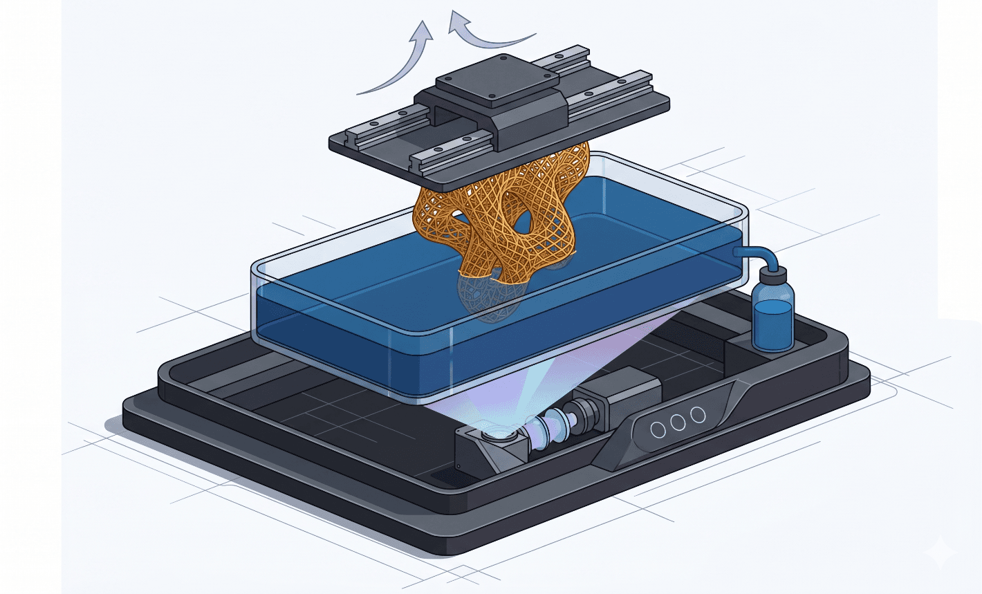
DLS projects a UV image through an oxygen-permeable window at the bottom of the resin vat. Oxygen forms a dead zone roughly 20 to 30 microns thick that prevents resin from sticking to the window, which lets the build platform pull the part upward continuously instead of peeling layer by layer.
Equally important, the green part is not the final part. Carbon's production resins are dual-cure: a UV network holds shape during printing, then a thermal cycle triggers a second chemistry — typically polyurethane — that develops the real mechanical properties.
| Attribute | SLA / DLP | Carbon DLS |
|---|---|---|
| Build motion | Layer peel | Continuous pull |
| Window interface | Adhesive release film | Oxygen-permeable dead zone |
| Cure stages | Single UV cure | UV + thermal second cure |
| Typical Z speed | 10–30 mm/hr | 60–120 mm/hr |
| Production resins | Limited | EPU, RPU, EPX, MPU, FPU, CE |
3D Printing: define requirements before selecting a process
Connect requirements, process decisions and inspection before the first build to reduce late design changes.
- 1Requirements
Function, service environment, quantity and failure risk
- 2Material and process
Material grade, build strategy, geometry and finishing
- 3Inspection
Critical dimensions, functional tests and lot records
Key design rules
The DFM Numbers Carbon Partners Actually Hold
Projected-light resolution tempts designers to specify features that survive the print but fail post-cure or handling. The numbers below are the ones service bureaus quote without a conversation; anything below them should be reviewed part by part.
| Feature | Rigid resins | Elastomers | Notes |
|---|---|---|---|
| Minimum wall | 1.0 mm | 1.5 mm | Below this, warp after cure rises sharply |
| Minimum strut (lattice) | 0.8 mm | 0.6 mm | Elastomers tolerate finer struts |
| Positive text | 0.4 mm depth, 1.5 mm tall | Not recommended | Use recessed text on EPU |
| Clearance / assembly gap | 0.3 mm | 0.5 mm | Increase for mating rigid + flex |
| Unsupported overhang | 1.0 mm | 0.5 mm | Above this, add supports |
The Two-Part Cure That Decides the Part
Green parts leave the printer in a solvent-swollen, partially networked state. Standard post-processing is to spin or wash away unreacted resin in Carbon's Smart Part Washer (typically a two-stage IPA then clean solvent sequence, 5 minutes each), dry fully, and only then move to the thermal oven.
The oven cycle itself is resin-specific. EPU 41 wants 120 C for 4 hours; RPU 70 uses 120 C for 4 hours as well but on a different ramp; EPX 82 pushes to 130 C for 2 hours; CE 221 is the outlier at 190 C for 2 hours followed by a secondary ramp.
From prototyping and finishing to acceptance
Where DLS Beats Molding on Volume Math
The old rule that injection molding wins above 1,000 units is too coarse for parts with elastomer, lattice, or revision-heavy content. Once you account for tooling amortization, revision costs, and the option value of geometry changes mid-run, DLS stays competitive from roughly 200 units up to 50,000, depending on part size and resin.
3D Printing: four checks before RFQ
- Function
State what the part must do and where it will be used
- Material and process
Name the required grade or performance range
- Design controls
Mark critical geometry, orientation and finishing
- Acceptance
Define dimensions, tests and required records
Pre-RFQ review: recommended practice and common mistakes
| Recommended practice | Common mistake |
|---|---|
| Select resin before locking geometry | Design in a generic rigid plastic then pick resin later |
| Judge dimensions at the post-cure state | Approve drawings against green-state measurements |
| Use lattice to break up thick sections | Leave solid blocks above 8 mm |
| Parameterize every lattice cell | Hand-edit struts one by one |
| Validate oven cycles with witness coupons | Trust oven setpoint without data logging |
- Resin selected and DFM rules applied resin-specifically
- All sections above 6 mm hollowed or lattice-filled
- Lattice struts parameterized and within resin-specific minimums
- Wash + dry time allocated before thermal cure
- Oven recipe matches the resin (temperature, time, ramp)
FAQ, further reading and sources
What should you define first for 3D Printing?
Define the operating environment, functional load, quantity and acceptance criteria before choosing a process. Those requirements determine the material, design rules and inspection plan.
Can the typical values in this guide be released directly on a drawing?
No. Use them for early design, then confirm the exact grade, supplier capability, DFM response and first-article result.
What should be locked before scaling production?
Lock the material, process settings, orientation, finishing and inspection method. Confirm that different lots reproduce the first-article result before scaling.
Next, explore 3D printing services, materials, online quoting, and the related design guides linked below.