Designing Thin Walls, Tight Clearances, and Fine Channels That Actually Ship
Content in this Article
3D Printing can look straightforward in CAD and still fail after printing, finishing or inspection. The useful question is not whether a process can make the geometry once, but whether the chosen material, orientation and acceptance method can deliver the required function repeatedly. This guide turns that decision into a practical review workflow.
- Define the operating environment, functional load, quantity and acceptance criteria before choosing a process.
- Treat dimensions and performance values as design-starting points; confirm the exact grade and supplier capability before release.
- Use a first article or pilot lot to lock inspection and process controls before scaling.

Start with requirements and process selection
Why Small Features Fail
Small features fail through four mechanisms, and a good fix usually names which one is at work before picking a number. Material behaviour — swelling, cure shrinkage, thermal contraction — can move a nominal 0. 3 mm gap by tens of microns in either direction.
| Failure mechanism | Where it bites | Magnitude you should plan for |
|---|---|---|
| Cure / sinter shrinkage | Gaps close, walls shrink | 0.3–0.8% of nominal (resin); 2–4% (polymer powder post-cool) |
| Post-processing addition | Vapour smoothing, paint | +0.05–0.15 mm per surface |
| Post-processing removal | Bead blasting, manual sanding | -0.05–0.15 mm per surface |
| Support removal damage | Down-facing walls, rib roots | Localised chip of 0.1–0.5 mm |
| Trapped powder / resin | Enclosed channels, deep pockets | Feature becomes non-functional even if nominally printed |
| Handling flex / bend | Walls with aspect > 20:1 | Permanent distortion if unsupported |
Thin Walls Need Handling Margin, Not Process Minimums
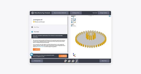
The minimum wall thickness in a process datasheet is a resolution number — it describes what the machine can form once, under ideal conditions, on a test coupon. It says almost nothing about what a wall has to survive on the way from the build plate to the customer. A wall that is going to be blasted, coated, handled, assembled, and used needs to sit meaningfully above the datasheet minimum.
3D Printing: define requirements before selecting a process
Connect requirements, process decisions and inspection before the first build to reduce late design changes.
- 1Requirements
Function, service environment, quantity and failure risk
- 2Material and process
Material grade, build strategy, geometry and finishing
- 3Inspection
Critical dimensions, functional tests and lot records
Key design rules
Clearances: Design for the Finished State, Not the Printed One
A clearance specified at the CAD stage is a clearance in the as-printed condition. Every finishing step after that is a chance for the clearance to change. Vapour smoothing adds roughly 0.
| Interface type | Recommended clearance (PA12 MJF, blasted) | Adjustment if also smoothed | Adjustment if also painted |
|---|---|---|---|
| Slip fit (cover, lid) | 0.3–0.4 mm | + 0.15 mm | + 0.1–0.3 mm per coat |
| Snap-fit beam engagement | 0.3 mm | + 0.1 mm | + 0.1 mm |
| Rotating hinge clearance | 0.5 mm | + 0.15 mm | + 0.15 mm |
| Press-fit (interference) | −0.05 to −0.1 mm (undersize) | Re-validate after smoothing | Avoid paint on mating surfaces |
| Sliding / linear rail | 0.4 mm | + 0.15 mm | Avoid paint on the rail |
| Sealing land (static O-ring) | Groove depth sized to compression | Re-inspect after any coating | Avoid paint in groove |
Channels, Slots, and Internal Access
A channel that cannot be cleaned is not a manufacturable feature. This is the first question to ask about any narrow internal geometry, and it is the question most often skipped. The process defines the minimum cleanup-feasible size, not the minimum print-feasible size.
| Process | Min print diameter | Min cleanup diameter | Required escape / drainage |
|---|---|---|---|
| SLS / MJF (polymer) | 0.8 mm | 1.5 mm straight-through, 3 mm blind | Two ≥ 4 mm escape holes per enclosed volume |
| DMLS / SLM | 0.4 mm | 1.0 mm + vibration-assist depowdering | Powder-evacuation orientation + escape ports |
| SLA / DLP | 0.5 mm | 1.0 mm with drain | ≥ 3 mm drain hole at the lowest orientation |
| FDM | 1.0 mm | 1.5 mm | Support material must be dissolvable or reachable |
| Carbon DLS | 0.5 mm | 1.5 mm with drain | Drain path for both wash and thermal-cure step |
| PolyJet | 0.3 mm | 1.0 mm with jet-wash access | Support gel rinse path from every channel |

From prototyping and finishing to acceptance
Oversize Parts: When the Geometry Is Bigger Than the Build Plate
A size-constrained design may also be size-constrained the other way — the part is simply too big to fit the platform. The fix is rarely to shrink the design; it is to split the geometry at a joint that makes structural sense, print the two (or more) halves, and rejoin them with a deliberate connection. Adhesive, mechanical joinery, or a moulded insert each have their place; the key is to design the joint as a feature, not leave it as a post-print reality.
| Joining method | Typical bond strength vs. parent material | When to use | Trade-off |
|---|---|---|---|
| Two-part epoxy | 60–80% | Non-structural joins, cosmetic | Visible seam; surface prep required |
| Dovetail / keyed interlock + adhesive | 80–95% | Structural joins with alignment | Requires precision print on the keyway |
| Threaded insert + fastener | Depends on fastener | Serviceable / disassemblable | Adds hardware and cost |
| Ultrasonic welding (polymer) | 70–90% | High-volume consumer | Only works with weldable thermoplastics |
| Snap-fit with secondary pin | 50–80% | Prototype assembly, low-load | Not suited to cyclic loading |
| Press-fit across split line | Metal: 40–70% | Metal parts needing field-removable seams | Needs machined tolerance; align difficulty |
3D Printing: four checks before RFQ
- Function
State what the part must do and where it will be used
- Material and process
Name the required grade or performance range
- Design controls
Mark critical geometry, orientation and finishing
- Acceptance
Define dimensions, tests and required records
Pre-RFQ review: recommended practice and common mistakes
| Recommended practice | Common mistake |
|---|---|
| Design walls, gaps, and channels with handling + finishing margin | Design to the process minimum and hope |
| State the finish condition the clearance applies to | Leave clearance unmarked as to pre- or post-finish |
| Design escape paths for every enclosed internal geometry | Assume the printer's cleanup will reach anywhere |
| Split oversize parts at structurally sensible joints | Redesign the whole geometry to fit a smaller bed |
| Validate tight features on real mating hardware | Validate small features only on isolated coupons |
| Re-check clearances after vapour smoothing or paint | Treat post-processing as dimensionally neutral |
- Every wall has a handling margin above the datasheet minimum; critical walls include finishing allowance.
- Every clearance specifies the finish state it applies to (raw / blasted / smoothed / painted).
- Every enclosed internal volume has an escape path sized to the cleanup minimum, not the print minimum.
- Channels longer than 40 mm have either two escape routes or a verified orientation that lets material flow out.
- Oversize parts are split at structurally logical joints, not at cosmetic surfaces.
FAQ, further reading and sources
What should you define first for 3D Printing?
Define the operating environment, functional load, quantity and acceptance criteria before choosing a process. Those requirements determine the material, design rules and inspection plan.
Can the typical values in this guide be released directly on a drawing?
No. Use them for early design, then confirm the exact grade, supplier capability, DFM response and first-article result.
What should be locked before scaling production?
Lock the material, process settings, orientation, finishing and inspection method. Confirm that different lots reproduce the first-article result before scaling.
Next, explore 3D printing services, materials, online quoting, and the related design guides linked below.