What Is Design for Additive Manufacturing: A Working Playbook
Content in this Article
DfAM creates value when geometry, volume, revision frequency and functional requirements fit additive manufacturing. This guide connects process, material, design and inspection decisions.
- Define function, environment, quantity and risk before selecting a material or process.
- Treat typical values as comparison points; confirm the exact grade and supplier capability before release.
- Use a first article or pilot lot to verify dimensions, function and records before scaling.

Define the decision
Document function, environment, quantity and risk so every option is compared against the same requirement.
The Mindset Shift Behind DfAM
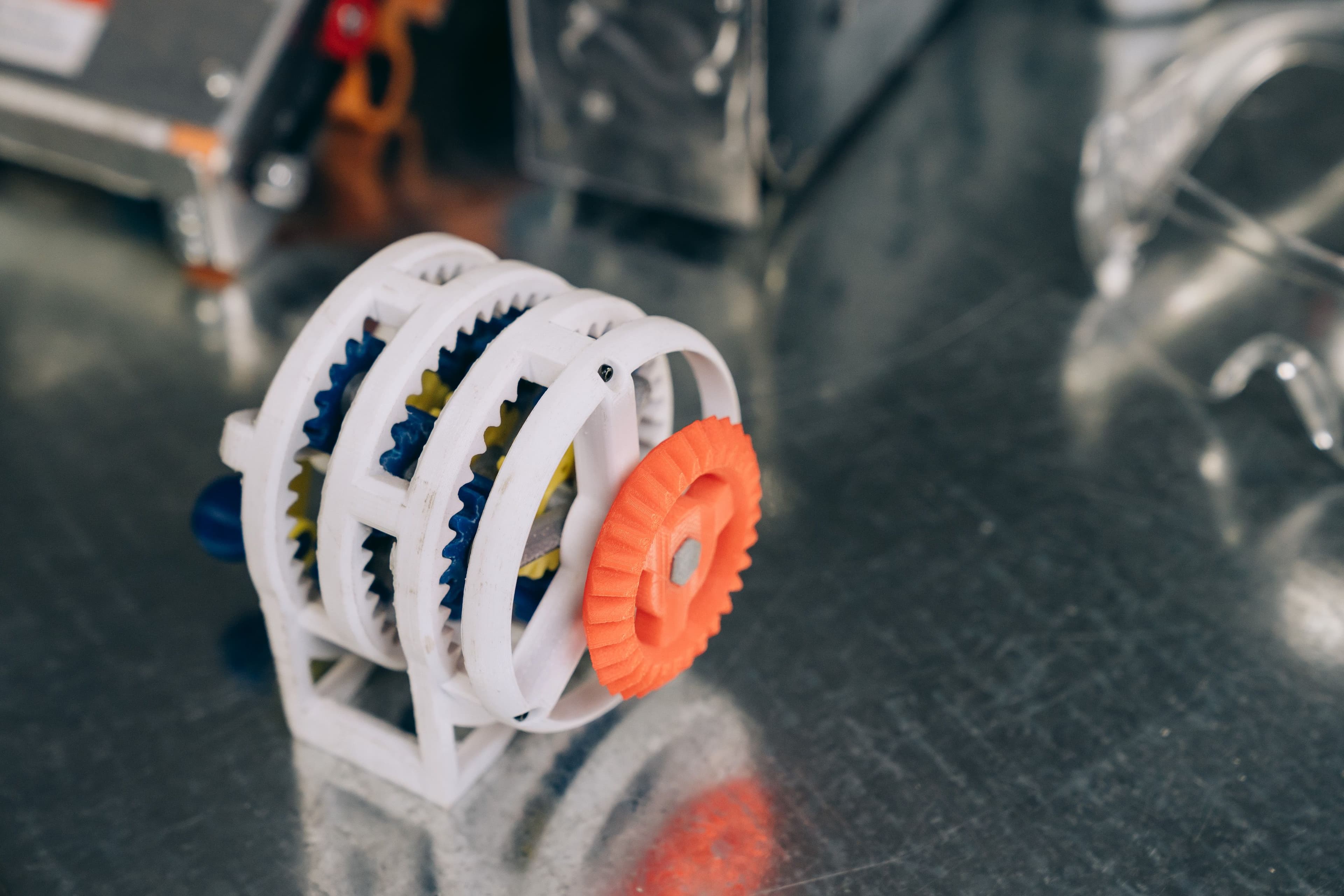
Traditional manufacturing imposes unconscious constraints: draft angles for molding, tool access for milling, bend radii for sheet metal. Additive removes most of them — internal lattices, conformal channels, and topology-optimized geometry are suddenly free.
| Dimension | Conventional Thinking | DfAM Thinking |
|---|---|---|
| Wall thickness | Uniform for strength | Varied 0.8–3.0 mm with stress |
| Assembly | Fasteners connect parts | Collapse 8 parts into 1 |
| Cooling | Straight drilled lines | Conformal to the surface |
| Tolerance | Tight everywhere | Tight only on mating faces |
| Mass | Whatever geometry needs | Topology-driven minimum |
The Six Principles That Anchor Every DfAM Review
A DfAM review is a small number of questions, asked in order. Orientation first — because it shapes everything downstream.
DfAM evaluation flow
Define requirements, narrow the material and process, then verify with a consistent acceptance method.
- 1Requirements
Function, environment, quantity and risk
- 2Options
Material, process, design controls and finishing
- 3Acceptance
Dimensions, functional tests and production records
Compare the practical options
Compare material, process, design controls and finishing together—not unit price alone.
Why Build Orientation Is the First Design Decision
Orientation sets anisotropy, surface quality, support location, build height, and nesting efficiency in one decision. A 120 mm housing oriented vertically prints 3.
Designing Supports Out of the Part
The cheapest support is the one you never had to print. Chamfer overhangs to 45 degrees, add sacrificial walls to turn unsupported islands into supported slopes, and orient holes horizontally only when their diameter exceeds 8 mm.
| Feature | Self-Supporting Limit | Fix |
|---|---|---|
| Overhang angle | 45° polymer, 35° metal | Chamfer the transition |
| Horizontal hole | Ø ≤ 8 mm teardrops | Teardrop or diamond cross-section |
| Bridge span | < 5 mm polymer, < 2 mm metal | Add a center pillar |
| Downward-facing surface | Always rougher | Orient upward if cosmetic |
| Internal channel | Ø ≥ 2 mm, smooth sweep | Avoid sharp turns |
Validate before scaling
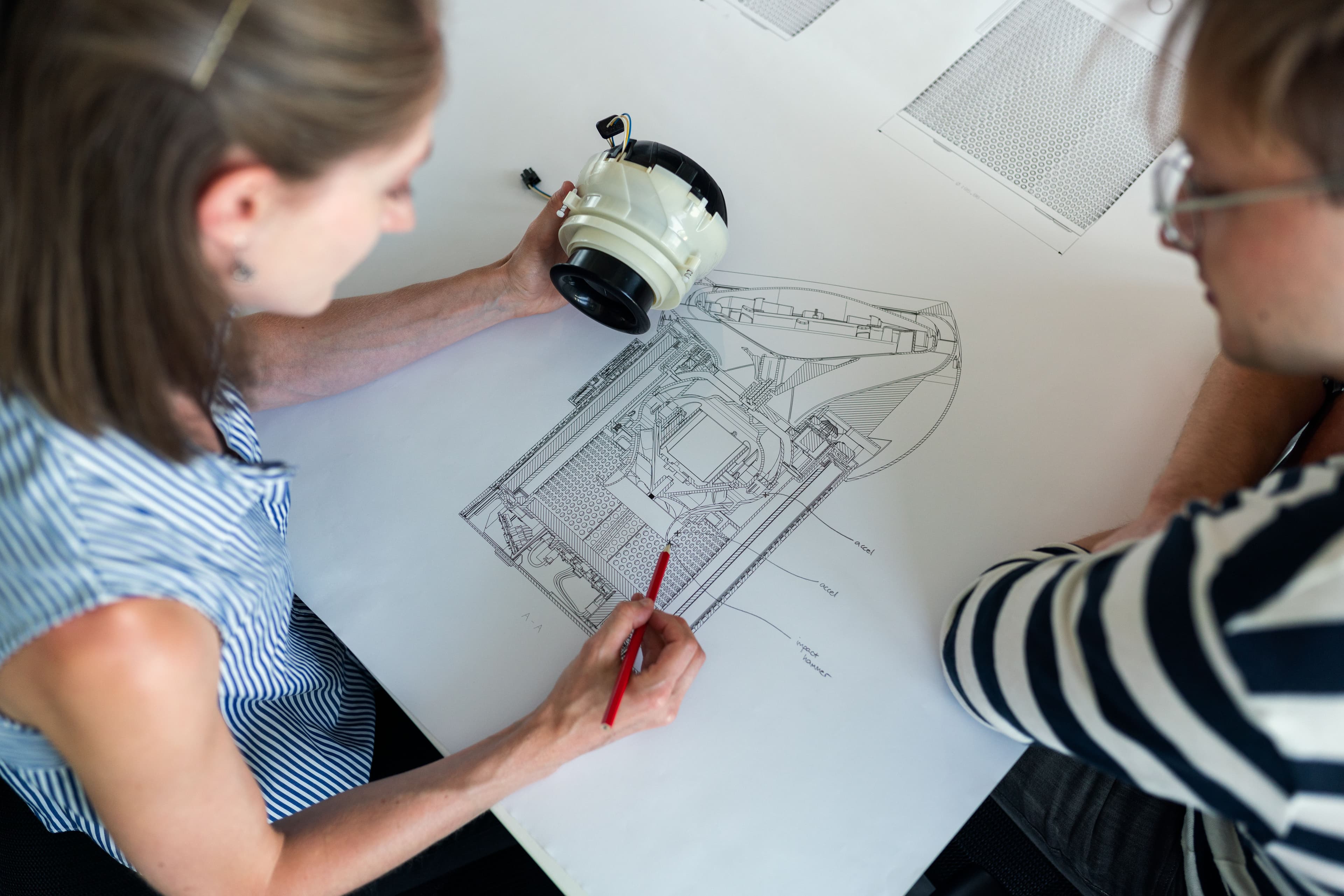
Before scaling, verify dimensions, function and records with one controlled method across representative lots.
Tolerances You Can Actually Hold
A common DfAM mistake is inheriting CNC tolerance blocks on an additive drawing. Most polymer processes hold ±0.
Mistakes That Show Up on Every DfAM Review
| Mistake | Why It Fails | How to Avoid |
|---|---|---|
| Drawing without an orientation arrow | Operator picks the fastest build | Lock orientation on the drawing |
| 0.4 mm wall on MJF | Part short-fills or warps | Raise to 0.8 mm minimum |
| Sealed hollow housing | Powder locks in at 30–80 g | Add two 3 mm drain holes |
| ±0.05 mm on a printed face | Process cannot hold it | Machine the feature post-print |
| M3 printed threads | Strip under 5 N·m | Heat-set insert or M4+ |
Pre-RFQ review: recommended practice and common mistakes
| Recommended practice | Common mistake |
|---|---|
| Document function, environment, quantity and risk | Select from a material name or machine specification alone |
| Review material, process, design controls and finishing together | Address manufacturing limits only after design freeze |
| Inspect critical dimensions and function on the first article | Scale production from visual approval alone |
| Keep material, revision and inspection records | Reuse old results after a material or process change |
- Function, environment, quantity and risk are documented
- Material, process, design controls and finishing are reviewed with the supplier
- Critical dimensions, appearance and functional acceptance are on the drawing or RFQ
- First-article or pilot-lot verification is planned
- Material, process and revision changes trigger a new review
FAQ, further reading and sources
What should be defined first for DfAM?
Start with function, environment, quantity and acceptance criteria. These inputs narrow the practical options faster than naming a machine or material first.
Can typical values in this article be released directly on a drawing?
No. Use them for early comparison, then confirm the exact grade, supplier capability and first-article result.
When is the process ready to scale?
Scale only after material, process, finishing and inspection are controlled and repeatable across representative lots.
Next, explore 3D printing services, CNC machining, materials, and the related reports linked on this page.