Overmolding and Insert Molding Without Delamination or Surprise Cycle Time
Content in this Article
Overmolding is easiest to control before tooling release. Align material, wall thickness, ejection, gating and acceptance criteria so appearance, dimensions and cycle time are considered together.
- Define function, environment, quantity and risk before selecting a material or process.
- Treat typical values as comparison points; confirm the exact grade and supplier capability before release.
- Use a first article or pilot lot to verify dimensions, function and records before scaling.
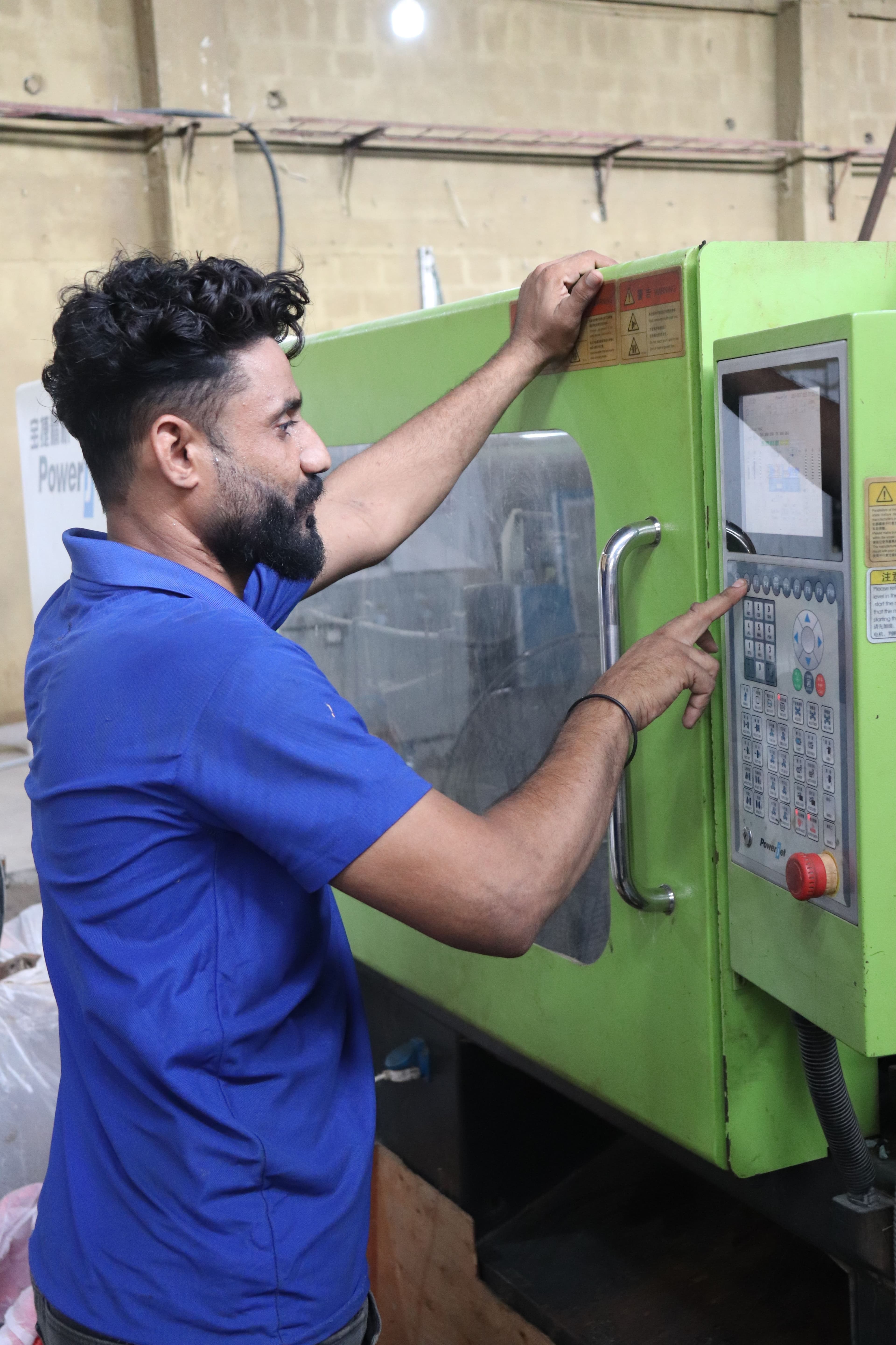
Define the decision
Document function, environment, quantity and risk so every option is compared against the same requirement.
Two Processes That Look Alike and Fail Differently
Overmolding shoots a second shot of plastic — usually a softer elastomer — onto a first-shot thermoplastic substrate. The failure mode you care about is delamination: a bond that looks fine on day one and peels in month three.
Many production parts use both at once — a PC housing with brass inserts for the fasteners plus a TPE overmold on the grip zone — and the two decisions interact. The insert position constrains where the second-shot gate can land; the overmold wall constrains how close to the part surface the insert boss can sit without sinking.
Material Pair Compatibility Is the Whole Game in Overmolding
The difference between a bond that passes 45 N and a bond that fails at 14 N is rarely the process setting. It is almost always the material pair.
If the grade sheet does not exist or the supplier cannot quote a number, treat the pair as unproven and plan a bench test: mold small plaques, cure 48 hours, and pull them on a 180° peel jig before any tool money is spent.
Overmolding evaluation flow
Define requirements, narrow the material and process, then verify with a consistent acceptance method.
- 1Requirements
Function, environment, quantity and risk
- 2Options
Material, process, design controls and finishing
- 3Acceptance
Dimensions, functional tests and production records
Compare the practical options
Compare material, process, design controls and finishing together—not unit price alone.
Mechanical Interlocks: Insurance When Chemistry Alone Is Not Enough
Even a chemically compatible pair should carry a mechanical interlock on any part that will see shear or pull loads. Holes through the substrate that the overmold fills, undercuts along the bond edge, and deliberate textured zones on the first-shot surface all give the second shot something to hold onto if the chemical bond degrades after UV exposure, thermal cycling, or months of skin oils.
Insert Design: Why Smooth Inserts Spin at 0.8 Nm
A cylindrical brass insert pressed into molten plastic looks captured — the plastic shrinks around it as it cools — but the joint is held entirely by friction and thermal shrink. In service, heat cycles loosen the grip and a smooth insert spins.
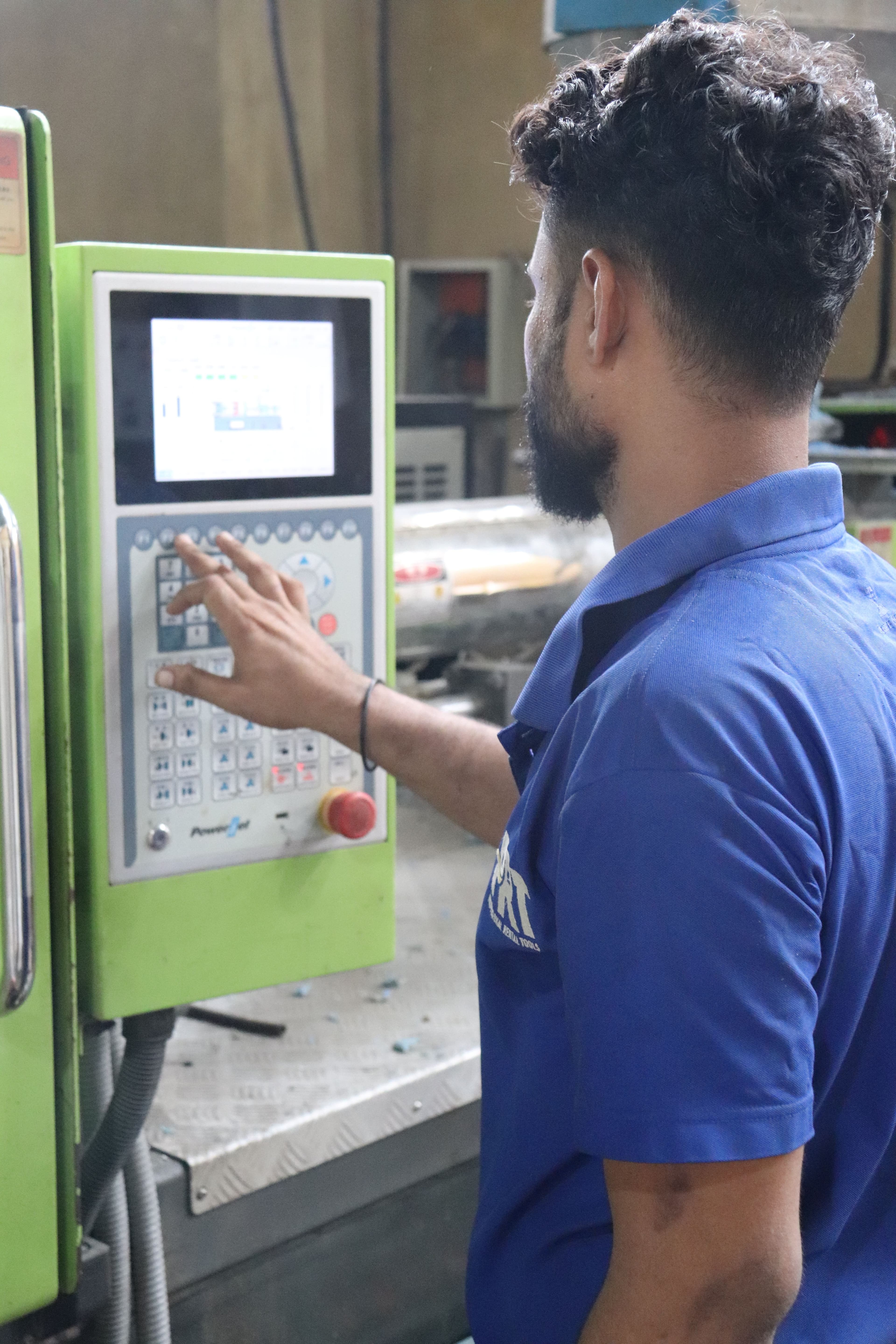
Validate before scaling
Before scaling, verify dimensions, function and records with one controlled method across representative lots.
Thermal Behaviour: The Metal Insert Is a Heat Sink
A brass insert at room temperature drops the local melt temperature as the plastic flows past it. If the temperature dips below the freeze point, the flow front stalls, leaving voids around the insert that look like micro-sinks on X-ray and feel soft on pull.
Tool Strategy: Two-Shot, Rotary, or Transfer
| Strategy | How It Works | Tool Cost Index | Cycle Impact | Best For |
|---|---|---|---|---|
| Multi-shot (rotary platen) | Core rotates between two cavities in one machine | 1.0× | Lowest — single cycle | High-volume, two-colour consumer parts |
| Transfer between machines | First shot on machine A, loaded into machine B | 0.55× | +20 – 40 s handling | Low volume, prototype to 10 k units |
| Core-back / rotary core | Core retracts in place to reveal second shot cavity | 1.3× | +3 – 8 s | Complex geometries with interior overmold |
| Insert-loaded | Robot places insert; one shot of plastic | 0.7× | +3 – 12 s loading | Insert molding, low-to-mid volume |
| Robotic overmold on first-shot | Robot carries first shot to second tool | 0.9× | +15 – 25 s | Medical, where cleanliness is critical |
Pre-RFQ review: recommended practice and common mistakes
| Recommended practice | Common mistake |
|---|---|
| Document function, environment, quantity and risk | Select from a material name or machine specification alone |
| Review material, process, design controls and finishing together | Address manufacturing limits only after design freeze |
| Inspect critical dimensions and function on the first article | Scale production from visual approval alone |
| Keep material, revision and inspection records | Reuse old results after a material or process change |
- Function, environment, quantity and risk are documented
- Material, process, design controls and finishing are reviewed with the supplier
- Critical dimensions, appearance and functional acceptance are on the drawing or RFQ
- First-article or pilot-lot verification is planned
- Material, process and revision changes trigger a new review
FAQ, further reading and sources
What should be defined first for Overmolding?
Start with function, environment, quantity and acceptance criteria. These inputs narrow the practical options faster than naming a machine or material first.
Can typical values in this article be released directly on a drawing?
No. Use them for early comparison, then confirm the exact grade, supplier capability and first-article result.
When is the process ready to scale?
Scale only after material, process, finishing and inspection are controlled and repeatable across representative lots.
Next, explore 3D printing services, CNC machining, materials, and the related reports linked on this page.