Solving Wall Thickness Issues in Injection-Molded Parts
Content in this Article
Injection Molding can look straightforward in CAD and still fail after printing, finishing or inspection. The useful question is not whether a process can make the geometry once, but whether the chosen material, orientation and acceptance method can deliver the required function repeatedly. This guide turns that decision into a practical review workflow.
- Define the operating environment, functional load, quantity and acceptance criteria before choosing a process.
- Treat dimensions and performance values as design-starting points; confirm the exact grade and supplier capability before release.
- Use a first article or pilot lot to lock inspection and process controls before scaling.
Start with requirements and process selection
Recommended Nominal Wall by Resin
Each thermoplastic has a viable wall window dictated by melt viscosity and shrinkage. The ranges below assume flow lengths under 150 mm and a single-cavity prototype tool; multi-cavity production may need the upper bound for balance.
| Resin | Min Wall (mm) | Typical (mm) | Max Wall (mm) | Shrink (%) |
|---|---|---|---|---|
| ABS | 2.0 | 2.5 | 3.5 | 0.4–0.7 |
| PC | 1.5 | 2.4 | 3.8 | 0.5–0.7 |
| PP | 0.8 | 1.5 | 2.5 | 1.5–2.5 |
| Nylon 6/6 | 1.5 | 2.0 | 3.0 | 1.0–2.0 |
| POM (Acetal) | 2.0 | 2.8 | 4.0 | 1.8–2.5 |
Sink Mark Predictors
Sink marks form when a thicker subsurface mass continues to shrink after the visible skin has frozen. Two ratios predict risk before the mold is cut: adjacent-thickness ratio and rib-to-wall ratio.
Injection Molding: define requirements before selecting a process
Connect requirements, process decisions and inspection before the first build to reduce late design changes.
- 1Requirements
Function, service environment, quantity and failure risk
- 2Material and process
Material grade, build strategy, geometry and finishing
- 3Inspection
Critical dimensions, functional tests and lot records
Key design rules
Ribbing and Coring Strategies
Stiffness comes from geometry, not mass. A 1.
| Feature | Rule | Reason |
|---|---|---|
| Rib thickness | ≤ 0.6× nominal wall | Avoid sink on opposite face |
| Rib height | ≤ 3× nominal wall | Avoid fill hesitation at tip |
| Rib draft | 0.5–1.0° per side | Ejection without scuffing |
| Rib spacing | ≥ 2× nominal wall | Cooling channels between |
| Boss OD | 2× ID, cored | Hollow column shrinks evenly |
Knit Lines and Flow Convergence
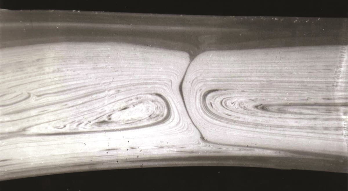
Wall thickness directly governs how cleanly flow fronts merge behind holes, inserts, or ribs. Thin walls cool the leading edges before they re-fuse, leaving a knit line with 30–70% of bulk tensile strength.
From prototyping and finishing to acceptance
Warp from Differential Cooling
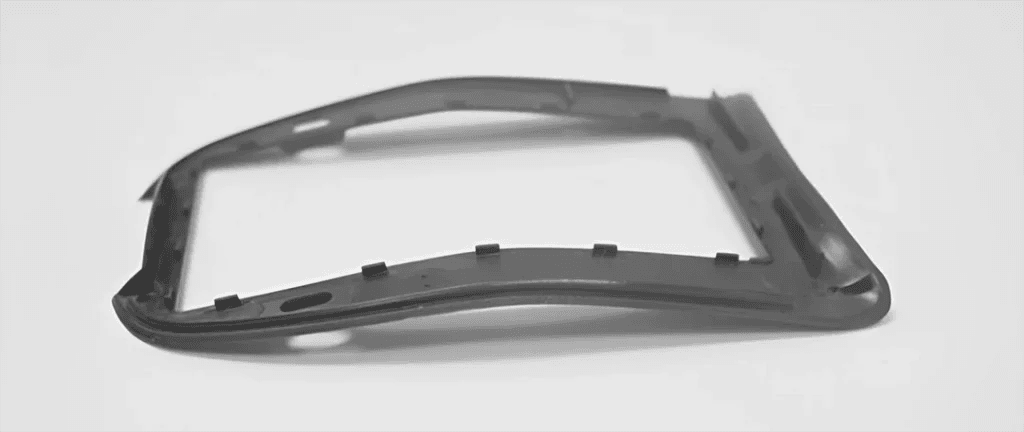
Warp is the macroscopic readout of uneven shrinkage. When one face of a wall cools faster than the other—because of mold-side coolant temperature, asymmetric ribs, or thickness steps—the part bends toward the slower-cooling side.
Fixes are geometric before they are processing-based: equalize wall thickness on both sides of any rib, place ribs symmetrically about the neutral axis, and use balanced cooling lines on the tool. Process levers (pack pressure, mold temp delta) only mask underlying geometry sins.
Injection Molding: four checks before RFQ
- Function
State what the part must do and where it will be used
- Material and process
Name the required grade or performance range
- Design controls
Mark critical geometry, orientation and finishing
- Acceptance
Define dimensions, tests and required records
Pre-RFQ review: recommended practice and common mistakes
| Recommended practice | Common mistake |
|---|---|
| Hold adjacent thickness within 1.25× of nominal | Step from 2 mm directly to 4 mm wall |
| Core every boss above 0.6× wall ratio | Use solid bosses for press-fit inserts |
| Gate into the thickest cross-section | Gate into a thin rim feeding thicker hub |
| Apply 0.5–1° draft on every vertical wall | Leave zero-draft cosmetic faces |
| Use generous fillets (0.25–0.5× wall) at junctions | Use sharp 90° internal corners |
- Nominal wall is within the resin's recommended window (see resin table)
- All adjacent-thickness ratios are at or below 1.25×
- Every boss is cored with OD ≤ 0.6× nominal wall
- Every rib is ≤ 0.6× wall thick and ≤ 3× wall tall
- Gate location feeds thick-to-thin without crossing a thin neck
FAQ, further reading and sources
What should you define first for Injection Molding?
Define the operating environment, functional load, quantity and acceptance criteria before choosing a process. Those requirements determine the material, design rules and inspection plan.
Can the typical values in this guide be released directly on a drawing?
No. Use them for early design, then confirm the exact grade, supplier capability, DFM response and first-article result.
What should be locked before scaling production?
Lock the material, process settings, orientation, finishing and inspection method. Confirm that different lots reproduce the first-article result before scaling.
Next, explore 3D printing services, materials, online quoting, and the related design guides linked below.