Sheet Metal Bend Radius: Working Numbers for Steel, Stainless, and Aluminum
Content in this Article
Sheet Metal can look straightforward in CAD and still fail after printing, finishing or inspection. The useful question is not whether a process can make the geometry once, but whether the chosen material, orientation and acceptance method can deliver the required function repeatedly. This guide turns that decision into a practical review workflow.
- Define the operating environment, functional load, quantity and acceptance criteria before choosing a process.
- Treat dimensions and performance values as design-starting points; confirm the exact grade and supplier capability before release.
- Use a first article or pilot lot to lock inspection and process controls before scaling.
Start with requirements and process selection
How to read the rules
Numbers below assume cold rolling, room temperature, and an air-bend on a standard 88 degree V-die. Coining and bottoming reduce springback but require 5 to 10 times the air-bend tonnage.
Treat thickness (t) as the master variable: minimum IR, hole-to-bend distance, bend-to-edge distance, and slot proximity all scale from t. When in doubt, prototype with the largest IR your envelope tolerates, then tighten only after a successful trial.
Minimum inside bend radius by material and thickness
| Material | 0.5 mm | 1.0 mm | 1.5 mm | 2.0 mm |
|---|---|---|---|---|
| Steel 1010 (CRS) | 0.5 mm (1.0 t) | 1.0 mm (1.0 t) | 1.5 mm (1.0 t) | 2.0 mm (1.0 t) |
| 304 stainless | 0.8 mm (1.6 t) | 1.6 mm (1.6 t) | 2.4 mm (1.6 t) | 3.2 mm (1.6 t) |
| 5052-H32 aluminum | 0.5 mm (1.0 t) | 1.0 mm (1.0 t) | 1.5 mm (1.0 t) | 2.0 mm (1.0 t) |
| 6061-T6 aluminum | 1.5 mm (3.0 t) | 3.0 mm (3.0 t) | 4.5 mm (3.0 t) | 6.0 mm (3.0 t) |
Sheet Metal: define requirements before selecting a process
Connect requirements, process decisions and inspection before the first build to reduce late design changes.
- 1Requirements
Function, service environment, quantity and failure risk
- 2Material and process
Material grade, build strategy, geometry and finishing
- 3Inspection
Critical dimensions, functional tests and lot records
Key design rules
Hole, slot, and edge distances
Forming distorts material within roughly 4 t of the bend line. Holes inside that zone deform into ovals; tabs split; threaded inserts wander out of position.
| Feature | Min distance from bend line | Min distance from edge | Notes |
|---|---|---|---|
| Round hole | 2.5 t + IR | 2.0 t | Measured edge-to-edge |
| Slot (parallel) | 4.0 t + IR | 2.5 t | Long axis along bend |
| Slot (perpendicular) | 3.0 t + IR | 2.5 t | Bridges deform less |
| PEM stud / nut | 3.0 t + IR | 2.0 D | D = insert diameter |
Where geometry forces a violation, add bend reliefs: a 1. 5 t wide x 1.
From prototyping and finishing to acceptance
Sheet Metal: four checks before RFQ
- Function
State what the part must do and where it will be used
- Material and process
Name the required grade or performance range
- Design controls
Mark critical geometry, orientation and finishing
- Acceptance
Define dimensions, tests and required records
Pre-RFQ review: recommended practice and common mistakes
| Recommended practice | Common mistake |
|---|---|
| Use IR equal to material thickness as the starting point | Specify zero-radius or sharp bends on production drawings |
| Add bend reliefs 1.5 t wide and 1.5 t deep at flange ends | Run holes within 2.5 t of the bend without relief |
| Bend transverse to rolling direction on stainless | Bend 6061-T6 below 3 t inside radius |
| Specify tolerances on flange length, not bend angle | Stack bend angle tolerances tighter than plus or minus 0.5 deg |
- Confirm material grade, temper, thickness, and grain direction on the purchase release.
- Verify minimum inside bend radius against the matrix above for every bend on the part.
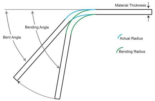
- Run BA = (pi/180) x angle x (IR + K x t) on at least one bend and compare with CAD flat pattern.
- Check hole, slot, and PEM distances against 2.5 to 4 t plus IR placement rules.
- Specify V-die width on the routing sheet using V = 6 to 10 t.
FAQ, further reading and sources
What should you define first for Sheet Metal?
Define the operating environment, functional load, quantity and acceptance criteria before choosing a process. Those requirements determine the material, design rules and inspection plan.
Can the typical values in this guide be released directly on a drawing?
No. Use them for early design, then confirm the exact grade, supplier capability, DFM response and first-article result.
What should be locked before scaling production?
Lock the material, process settings, orientation, finishing and inspection method. Confirm that different lots reproduce the first-article result before scaling.
Next, explore 3D printing services, materials, online quoting, and the related design guides linked below.